


Mascot FT Floor Standing Combination Boiler
Page 49
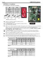
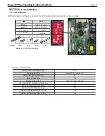
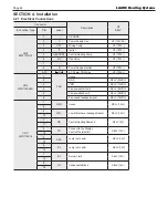
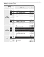
4.21 Electrical Connections
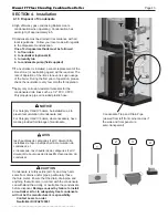
SECTION 4. Installation
Connector
Description
HT
SELV
#, Location, Type
PIN
Label
CN7
LWD1140-14
1
F.S
Flame Detect Sensor
SELV (5VDC)
8
2
OP.S
Operation water temperature sensor
SELV (5VDC)
9
3
DH.S
DHW temperature sensor
SELV (5VDC)
10
4
I.S
CH Return sensor
SELV (5VDC)
11
5
BG.S
Exhaust temperature sensor
SELV (5VDC)
12
6
ST.S
Storage water temperature sensor
SELV (5VDC)
13
7
SP.S
Over heat temperature sensor
SELV (5VDC)
14
CN14
SMW250-09D
1
IWM
GND
SELV (14VDC)
2
DHM Stepper motor position
SELV (14VDC)
3
VDD
SELV (14VDC)
4
DHM Stepper motor coil X phase
SELV (14VDC)
5
DHM Stepper motor coil Y phase
SELV (14VDC)
6
VDD
SELV (14VDC)
7
DHM Stepper motor coil /X phase
SELV (14VDC)
8
DHM Stepper motor coil /Y phase
SELV (14VDC)
9
Unuse
-
CN3
SMW250-06D
1
APS
SEN-
SOR
VCC
SELV (5V)
2
GND
SELV (5V)
3
Voltage input
SELV (5V)
4
FLUX1
VCC
SELV (5VDC)
5
Water Flow Sensor
SELV (5VDC)
6
GND
SELV (5VDC)
Summary of Contents for MFTCF140
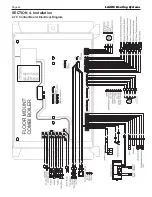
Page 48: ...LAARS Heating Systems Page 46 4 19 Control Board Electrical Diagram SECTION 4 Installation...
Page 65: ...Mascot FT Floor Standing Combination Boiler Page 63 6 2 Fault Tree Analysis 1 Flame detection...
Page 75: ...Mascot FT Floor Standing Combination Boiler Page 73...
Page 78: ...LAARS Heating Systems Page 76 Heat Exchanger MFTCF140...


