9
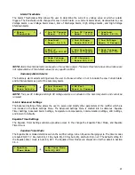
LEDs are provided on the inverter section for the following status indicators: Phase Lock, Auto Retransfer,
Manual Retransfer, Load on Preferred Source, Load on Alternate Source, Utility Available, Inverter Available,
Load Voltage, Load Current, Load VA, Utility Voltage, Utility Frequency, Inverter Voltage, and Inverter
Frequency. Refer to Figure 8 below.
All alarm contacts for the S2A-198 relay board are designed to be fail-safe. In other words, if both the AC and
DC power are removed, each alarm will be indicating in its correct state. To accomplish this, certain alarm
relays are de-energized on failure (such as Low DC Current), and certain alarm relays are energized on failure
(such as High DC Voltage). Refer to Table 6 for the logic of each alarm and refer to Table 7 for alarm contact
specifications.
Figure 8
–
S2A-240 Display Board
S2A-198 Relay Information
Relay Function
Logic
AC Power Fail
De-Energize On Fail
Summary
De-Energize On Fail
High DC Voltage
Shutdown
Energize On Fail
Low DC Current
De-Energize On Fail
High DC Voltage
Energize On Fail
Low DC Voltage
De-Energize On Fail
End of Discharge
De-Energize On Fail
Positive Ground
Energize On Fail
Negative Ground
Energize On Fail
Phase Locked
De-Energize On Fail
Utility Available
De-Energize On Fail
Inverter Available
De-Energize On Fail
Load on Preferred
Source
De-Energize On Fail
Load on Alternate
Source
De-Energize On Fail
Table 6
–
Alarms Relay Logic
Load Resistive Load (P.F. = 1)
Contact Material Ag (Au clad)
Maximum Allowed Current 2 A
Max. Operating Voltage and
Current
0.5 A at 125 VAC
0.6 A at 110 VDC
2.0 A at 30 VDC
Max. Switching Capacity
62.5 VA
60 W
Min. Permissible Load 10 µA / 10 mVDC
Table 7
–
Alarm Contact Specifications
Summary of Contents for AUPS-2K-A1-ABD1-24V150A
Page 30: ...24 3 6 3 Rectifier Customer Configuration Menu AUPS Rectifier Customer Configuration Menu...
Page 31: ...25...
Page 32: ...26...


