background image


32 


An ideal mounting place for the thermo-hygro sensor would be the outer wall beneath the 
extension of a roof, as this will protect the sensor from direct sunlight and other extreme 
weather conditions. Be sure to mount vertically. 


To wall mount, use the 2 screws to affix the wall bracket to the desired wall, plug in the 
thermo-hygro sensor to the bracket and secure both parts by the use of the supplied screw 
and ensure that the cable from the wind sensor is correctly plugged in otherwise data 
transmission errors could occur.


The Wind Sensor 


Check that the wind-cups can rotate freely before fixing the unit.  For correct and accurate 
readings, it is important to mount the sensor with the cups on the bottom.  The wind 
sensor should now be mounted using the screw or cable tie provided onto a solid wall/ 
panel mast or mast to allow the wind to travel around the sensor unhindered from all 
directions (ideal mast size should be from diameter 0.62” to 1.29” (16mm to 33mm). Do 
not over tighten the mounting bracket 

Once the wind sensor is fixed onto the mast, connect the cable to the corresponding 
thermo-hygro sensor socket so that operating power supply can be received and data can 
be transmitted to the base station. Secure cord from blowing. Do not use staples. Using 
PVC pipe or metal as a mast may cause static. Wood is recommended. 


Wind -cups 

Horizontal panel 

Vertical 
mast 

Summary of Contents for WS- 1913

Page 1: ...1 WS 1913 WEATHER CENTER Instruction Manual...

Page 2: ...creen 12 Manual settings 14 Weather forecast and weather tendency 18 Wind speed measurement 21 Rainfall measurement 21 Viewing history data 22 Viewing the MIN MAX weather data 23 Outdoor transmission...

Page 3: ...st Pages after pages you will discover that the operation of your weather station is really simple INVENTORY OF CONTENTS 1 Wireless Weather Station WS 1913U IT 2 Wireless Thermo hygro Sensor TX31U IT...

Page 4: ...or m s Wind speed displayed in km h mph or m s 24 hour and total rainfall displayed in mm or inch optional Display MIN MAX value of outdoor temperature outdoor humidity dew point wind chill and relat...

Page 5: ...the Weather Center at 915 MHz open air Rain resistant casing Wall mounting case to be mounted vertically in a sheltered place Avoid direct rain and sunshine The Wind sensor Connected to the thermo hy...

Page 6: ...rating the Weather Station it is important to completely set up the wiring and rest of the system in close proximity e g on a table 5ft 10ft from display and test all components for correct function b...

Page 7: ...ption icon is now blinking again to indicate that the station is trying to get the rain sensor data It will stop blinking once the rain sensor has been detected If this does not happen after 135 secon...

Page 8: ...mitters to redo set up procedure After batteries are installed there will be synchronization between Weather Center and the transmitters At this time the signal reception icon will be blinking When th...

Page 9: ...ing the setting up procedures This is because the thermo hygro sensor at start up assigns a random security code and this code must be received and stored by the Weather Center in the first several mi...

Page 10: ...owing the setting up procedures This is because the transmitter and rain sensor optional assign a random security code at start up and these codes must be received and stored by the Weather Station in...

Page 11: ...s shown for 30 seconds Then it returns to the normal display Press to activate the reset mode when MAX or MIN record is shown key In display Mode 1 press to toggle between the display of date weekday...

Page 12: ...r the last reception was successful ON icon or not OFF icon On the other hand the short blinking of the icon shows that a reception is being done at that time In normal display mode user may press the...

Page 13: ...icon Outdoor temp icon Rel Air Pressure icon Wind gust icon Dew point icon In Mode 1 this reception icon is showing the condition of the reception of the signal from Thermo hygro transmitter In Mode...

Page 14: ...pressure reference value setting Weather tendency threshold value Storm warning threshold value LCD CONTRAST SETTING The LCD contrast has 8 levels from LCD 1 to LCD8 default setting is LCD 5 1 Press...

Page 15: ...t to 24h time display 1 Use the or MIN MAX key to toggle the value 2 Confirm with the SET key and enter the CALENDAR SETTING CALENDAR SETTING The date default of the Weather Station is 1 1 of year 200...

Page 16: ...lometer per hour or m s meter per second The default unit is mph 1 Use the or MIN MAX key to toggle between the unit mph km h or m s 2 Confirm with the SET key and enter the RAINFALL UNIT SETTING RAIN...

Page 17: ...ion above sea level Ask for the current atmospheric pressure of your home area Local weather service www calibrated instruments in public buildings airport The relative air pressure can be manually se...

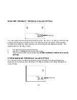
Page 18: ...ensitive the weather forecast The default value is 0 09 inHg 3 hPa 1 The threshold value will start flashing 2 Use the or MIN MAX key to select the value 3 Confirm with the SET key and enter the STORM...

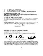
Page 19: ...ORM WARNING ICON When the storm warning threshold is reached you will see the cloud with rain icon and the down arrow will flash There is not an audible alarm WEATHER FORECAST AND WEATHER TENDENCY WEA...

Page 20: ...he Weather station will be more accurate compared to use in areas where the weather is stagnant most of the time for example mostly sunny If the Weather station is moved to another location significan...

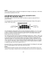
Page 21: ...esents the air pressure changes in inHg 0 12 0 06 0 0 06 0 12 The 0 represents the current air pressure The newly measured pressure was compared to the previously recorded pressure reading The pressur...

Page 22: ...ASUREMENT OPTIONAL The total rainfall and 24 hour rainfall measurement is displayed in the last section of the LCD where pressure is normally displayed in the unit of mm or inch To View the 24 hour ra...

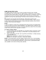
Page 23: ...history records you shall manually set the current time as soon as installing batteries to the weather station Afterwards you should avoid changing the pre set time as it will also alter the recorded...

Page 24: ...will be exhibited in whole number no decimal place in the history record VIEW THE MAXIMUM MINIMUM WEATHER DATA The weather station will record the minimum and maximum value of the various weather dat...

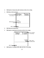
Page 25: ...nt temperature 4 MAX dew point temperature 5 MIN outdoor humidity with the date and time of recording 6 MAX outdoor humidity with the date and time of recording MIN icon MIN Dew Point temp Time and da...

Page 26: ...mperature with the date and time of recording 9 MIN Relative pressure with the date and time of recording 10 MAX Relative pressure with the date and time of recording MIN icon MIN wind chill value Tim...

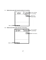
Page 27: ...MAX wind speed with the date and time of recording 12 MAX Gust with the date and time of recording MAX icon MAX wind speed value Time and date or recording MAX icon MAX Gust value Time and date or rec...

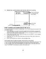
Page 28: ...on will appear at the bottom part of the LCD 3 Press the key once then the stored value will be reset to the current value and current time 4 Press the HISTORY key to return to normal display mode Tot...

Page 29: ...and the transmitter will be displayed in the second section and the low battery icon for the rain sensor optional will be shown on the last section of the LCD respectively when the battery power is lo...

Page 30: ...ast 5 to 6 5 feet 1 5 to 2 meters away from any interfering sources such as computer monitors or TV sets 2 Avoid positioning the Weather Center onto or in the immediate proximity of metal doors or win...

Page 31: ...riate connecter attached Please visit your local retailer or www lacrossetechnology com and click on the Buy button to locate an online dealer or other retailers Using phone cables or connections may...

Page 32: ...ly before fixing the unit For correct and accurate readings it is important to mount the sensor with the cups on the bottom The wind sensor should now be mounted using the screw or cable tie provided...

Page 33: ...tation i e when the reading interval is reached CARE AND MAINTENANCE Extreme temperatures vibration and shock should be avoided as these may cause damage to the unit and give inaccurate forecasts and...

Page 34: ...OF L if outside this range Outdoor dew point 40 F to 139 8 F with 0 2 F resolution 40 C to 59 9 C with 0 1 C resolution Displays OF L if outside this range Relative humidity measuring range Outdoor 1...

Page 35: ...local or and regional authorities to retrieve the addresses of legal dumping grounds with selective collection All electronic instruments must from now on be recycled User shall take an active part in...

Page 36: ...td will pay ground return shipping charges to the owner of the product to a USA address only Your La Crosse Technology Ltd warranty covers all defects in material and workmanship with the following sp...

Page 37: ...reserved This handbook must not be reproduced in any form even in excerpts or duplicated or processed using electronic mechanical or chemical procedures without written permission of the publisher Thi...

Reviews: