background image


20

The internal / external antennas used for this mobile SENSOR must provide a separation 
distance of at least 20 cm (8 inches) from all persons and must not be co-located or operating in 
conjunction with any other antenna or SENSOR." 
 

Statement according to FCC part 15.19: 

This device complies with Part 15 of the FCC Rules. Operation is subject to the following two 
conditions: (1) this device may not cause harmful interference, and (2) this device must accept 
any interference received, including interference that may cause undesired operation. 
 

Statement according to FCC part 15.21: 

Modifications not expressly approved by this company could void the user's authority to operate 
the equipment. 


Statement according to FCC part 15.105: 

NOTE: This equipment has been tested and found to comply with the limits for a Class B digital 
device, pursuant to Part 15 of the FCC Rules. These limits are designed to provide reasonable 
protection against harmful interference in a residential installation. This equipment generates, 
uses and can radiate radio frequency energy and, if not installed and used in accordance with 
the instructions, may cause harmful interference to radio communications. 
However, there is no guarantee that interference will not occur in a particular installation. If this 
equipment does cause harmful interference to radio or television reception, which can be 
determined by turning the equipment off and on, the user is encouraged to try to correct the 
interference by one or more of the following measures: 


Reorient or relocate the receiving antenna. 


Increase the separation between the equipment and receiver. 


Connect the equipment into an outlet on a circuit different from that to which the receiver is 
connected. 

Consult the dealer or an experienced radio/TV technician for help                      

Summary of Contents for WS-9077TWC-IT

Page 1: ...WS 9077TWC IT Wireless 915 MHz Weather Station Instruction Manual...

Page 2: ...Time Setting 9 12 24 hour Time Setting 9 Setting the Time 10 11 Setting the Year Day and Month 11 Setting the Snooze 12 Setting the Temperature Format 12 Setting the Forecast Sensitivity 13 Features W...

Page 3: ...AA 1 5V Alkaline batteries for the remote temperature sensor 3 One Philips screwdriver for mounting Figure 1 Time LCD Date LCD Forecast LCD Indoor LCD Outdoor LCD Figure 2 Mounting Bracket TX29U IT r...

Page 4: ...er Station and remote temperature sensor will begin to communicate with each other and the display will show both the indoor temperature and the outdoor temperature If the Wireless Weather Station doe...

Page 5: ...ed the Weather Station will start receiving data signal from the sensor The outdoor temperature should then be displayed on the Weather Station If this does not happen after 2 minutes the batteries wi...

Page 6: ...to normal time date readings If you don t leave the program mode during the programming of sections III through XII you can advance to step 4 of the next program setting If you do leave the program s...

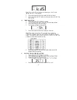
Page 7: ...for the U S is selected the corresponding abbreviation will appear above the time please see the table on the next page It is possible to select any time zone from 12 GMT to 12 GMT for example to see...

Page 8: ...hree times 4 RCC will appear in the date LCD and ON or OFF will flash in the time LCD 5 Press and release the IN button to select radio controlled time on or off 6 Press and release the SET button to...

Page 9: ...lly set the time or leave the time function alone reception will occur regardless After a successful reception no more reception attempt would be made until the following day B MANUAL TIME SETTING Not...

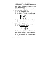
Page 10: ...SET button nine times 4 Either F or C will flash in the time LCD 5 Press and release the IN button to select the temperature format 6 Press and release the SET button to confirm and advance to the fo...

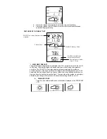
Page 11: ...r pressure readings to provide an accurate forecast creating a necessity to disregard all weather forecasting for 12 24 hours after the unit has been set up reset or moved from one altitude to another...

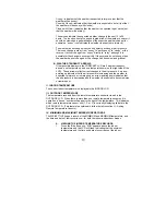
Page 12: ...down on the right side of the LCD These arrows reflect current changes in the air pressure An arrow pointing up indicates that the air pressure is increasing and the weather is expected to improve or...

Page 13: ...s before returning to the normal display mode 2 Press the OUT button again once while MIN is still displayed twice otherwise MAX appears above the outdoor temperature and the LCD will flash indicating...

Page 14: ...d sensor as soon as the channel 2 icon and outdoor data are displayed on the Weather Station Then within 2 minutes the channel 3 outdoor data from the third sensor will be displayed and the channel ic...

Page 15: ...OUTDOOR LCD within 4 minutes of setting up I THE REMOTE TEMPERATURE SENSOR The remote temperature sensor can be mounted in two ways with the use of screws or using the adhesive tape A MOUNTING WITH S...

Page 16: ...Be sure Weather Station is at least 6 feet from any electrical devices such as televisions computers or other radio controlled clocks 3 Remove batteries for five minutes reinsert and leave the unit a...

Page 17: ...nts or scouring agents they may mark the displays and casings Do not submerge in water Immediately remove all low powered batteries to avoid leakage and damage Opening the casings invalidates the warr...

Page 18: ...ur La Crosse Technology Ltd warranty covers all defects in material and workmanship with the following specified exceptions 1 damage caused by accident unreasonable use or neglect including the lack o...

Page 19: ...produced in any form even in excerpts or duplicated or processed using electronic mechanical or chemical procedures without written permission of the publisher This handbook may contain mistakes and p...

Page 20: ...imits for a Class B digital device pursuant to Part 15 of the FCC Rules These limits are designed to provide reasonable protection against harmful interference in a residential installation This equip...

Reviews: