background image

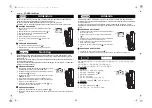
I.  THE REMOTE TEMPERATURE SENSOR 

The remote temperature sensor can be mounted in two ways: 

• 

with the use of screws, or 

• 

using the adhesive tape. 


A.  MOUNTING WITH SCREWS


1)  Remove the mounting bracket from the remote temperature 

sensor. 

2)  Place the mounting bracket over the desired location. 
3)  Through the three screw holes of the bracket, mark the 

mounting surface with a pencil. 

4)  Screw mounting bracket onto the mounting surface. Ensure 

that the screws are flush with the bracket. 

5)  Insert the remote temperature sensor into the bracket. 


B.  MOUNTING WITH ADHESIVE TAPE 

1) 

With a nonabrasive solution, clean and dry the back of the 
mounting bracket and the mounting surface to ensure a 
secure hold. The mounting surface should be smooth and 
flat. 

2) 

Remove the protective strip from one side of the tape. 

3) 

Adhere the tape to the designated area on the back of the 
mounting bracket. 

4) 

Remove the protective strip from the other side of the tape. 

5) 

Position the remote temperature sensor in the desired 
location, ensuring that the indoor weather station can 
receive the signal. 


16

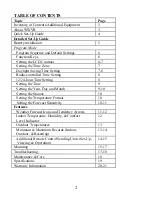
Summary of Contents for WS-9065TWC

Page 1: ...WS 9065U Wireless 433 MHz Radio controlled Weather Station Instruction Manual...

Page 2: ...2 24 hour Time Setting 8 Setting the Time 9 Setting the Year Day and Month 9 10 Setting the Snooze 10 Setting the Temperature Format 10 Setting the Forecast Sensitivity 10 11 Features Weather Forecast...

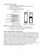
Page 3: ...in Ft Collins Colorado and transmits the exact time and date signal continuously throughout the United States at 60 kHz The signal can be received up to 2 000 miles away through the internal antenna...

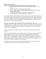
Page 4: ...n a dry shaded area The remote temperature sensor has a range of 330 feet Any walls that the signal will have to pass through will reduce distance An outdoor wall or window can have up to 30 feet of r...

Page 5: ...correct polarity and install 3 AA batteries 3 Replace the battery cover Note Immediately after the batteries have been installed the LCD Liquid Crystal Display will flash and a tone will sound Within...

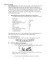
Page 6: ...ttings are as follows LCD Contrast 5 Time Zone 5 Eastern Daylight Saving Time 1 on Radio controlled time reception ON 12 24 hour time 12 Time 12 00 Year 2003 Day and Month 1 1 Snooze this function not...

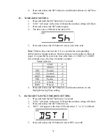
Page 7: ...please see the table on the next page It is possible to select any time zone from 12 GMT to 12 GMT for example to see the time in another country TIME ZONES GMT 0 Atlantic 4 EST Eastern 5 CST Central...

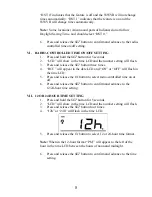
Page 8: ...button three times 4 RCC will appear in the date LCD and ON or OFF will flash in the time LCD 5 Press and release the IN button to select radio controlled time on or off 6 Press and release the SET bu...

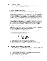
Page 9: ...nstallation you may manually set the time or leave the time function alone reception will occur regardless B MANUAL TIME SETTING Note When in the 12 hour format P M will appear to the left of the hour...

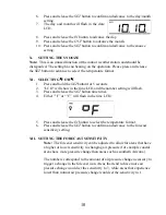
Page 10: ...the time LCD and the number setting will flash 3 Press and release the SET button nine times 4 Either F or C will flash in the time LCD 5 Press and release the IN button to select the temperature form...

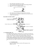
Page 11: ...tion Forecast icon Comfort Level Indicator The weather forecasting feature is estimated to be 75 accurate and is for the next 12 to 24 hours The weather forecast is based solely upon the change of air...

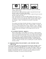
Page 12: ...t changed or the change has been slow and gradual B WEATHER TENDENCY ARROWS Other possible displays in the FORECAST LCD are 2 weather tendency arrows one that points up on the left side of the LCD and...

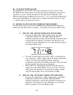
Page 13: ...with the humidity measured at that time and the time and date of occurrence are displayed The minimum records will display for 30 seconds before returning to the normal display mode 2 Press the IN but...

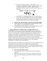
Page 14: ...ir own set of instructions follow these instructions for a complete guide to setting up Following are some brief instructions for the basic set up of remote temperature sensor units with the WS 9065U...

Page 15: ...you wish to reset Press and hold the OUT button for 5 seconds the records for the selected remote temperature sensor unit will be reset MOUNTING Note Before permanently mounting ensure that the indoo...

Page 16: ...hat the screws are flush with the bracket 5 Insert the remote temperature sensor into the bracket B MOUNTING WITH ADHESIVE TAPE 1 With a nonabrasive solution clean and dry the back of the mounting bra...

Page 17: ...indoor temperature station onto the screw using the hanging hole on the backside Gently pull the station down to lock the screw into place TROUBLESHOOTING NOTE For problems not solved please contact...

Page 18: ...ffect of the display s case In addition the case can act as a heat sink to absorb and store heat from external sources i e handling of the case or radiant heat Also the much greater range of the outdo...

Page 19: ...ndoor Temperature checking interval Every 10 seconds Indoor Humidity checking interval Every 1 minute Outdoor Temperature checking interval Remote Control Sender Every 1 minute Outdoor Temperature rec...

Page 20: ...nter La Crosse Technology Ltd will pay reasonable return shipping charges to the owner of the product Your La Crosse Technology Ltd warranty covers all defects in material and workmanship with the fol...

Page 21: ...ce must accept any interference received including interference that may cause undesired operation FCC ID OMO 01RX Receiver OMO 01TX transmitter Freq 433 92 MHz La Crosse Technology Made in China WS 9...

Reviews: