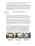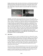
Using the spreader system, there are 3 cables to operate the hopper door (far left cable),
the diffuser (middle cable) and the deflector shield (lower right cable). By pulling on the
far left hopper door cable, this will open the door and allow product to fall on the spinner.
Adjustments as to how wide the door opens are made on the front on the hopper with the
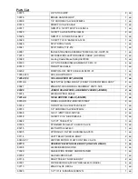
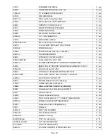
Hopper Rate Dial (Ref # 37 on page 17). This limits how wide the door will open and
how much granular product will be coming out. The diffuser cable (middle cable)
controls the spray pattern. Turning the cable knob counter-clockwise will loosen the
cable lock and allow you to adjust (pull further out or push further in) this cable. Doing
this will allow you to spread granular product heavier to the left, consistent in the middle
or heavier to the right. Once you have adjusted to your desired pattern, turn the knob
clockwise to lock in position.
The lower cable on the far right hand side is the deflector shield cable. This cable allows
you to lift and lower the deflector shield accordingly. During normal spreading
applications, the deflector shield would stay in the up position and cable would be
extended out all the way. When wanting to close off the left side and use the deflector
shield, push in the cable and the shield will drop down blocking off granular product on
the left side.
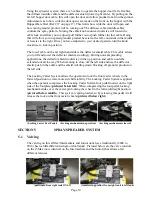
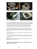
The Locking Caster System allows the operator to lock the front caster wheels in the
forward position to create more side hill stability. The Locking Caster System is applied
when the operator compresses the Locking Caster System foot pedal located on the right
side of the footplate (
pictured below left
). When compressing the foot pedal, locking
mechanism slides over the caster pin locking the wheel in the forward/straight position
(
pictured below middle
). This system is spring loaded, so by releasing this pedal it will
release the lock on the front caster wheels (
pictured below right
).
(Locking Caster Foot Pedal) (Locking mechanism in operation) (Locking mechanism released)
SECTION 5
SPRAY/SPREADER SYSTEM
5.1
Valving
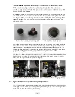
The valving on this Z-Max/Intermediate and Junior units have traditionally (2004 to
2014) been a little different (single or dual tanks). Pictured below are the valve controls
on the Z-Max (now identical on the Intermediate and the Junior) that allows a few
different features.
(
pull liquid from right tank ONLY)
(transferring product from right tank to left tank)
Page 10
Summary of Contents for Z-Spray
Page 1: ...OWNERS MANUAL Z Spray 60 Gallon Z Max 30 Gallon Intermediate Junior ...
Page 2: ......
Page 21: ...120 lb 220 lb Hopper Parts Page 17 ...
Page 22: ...Page 18 ...
Page 23: ...Z Max Intermediate Junior Manifold Assembly Page 19 ...
Page 24: ...Z Max Intermediate Junior Liquid Valve Assembly Page 20 ...
Page 25: ...Intermediate Junior Boom Assembly Page 21 ...
Page 26: ...Z Max Boom Assembly Page 22 ...
Page 35: ...Wiring Harness Page 31 ...


