background image

Kystar KS800 2K HD Big LED Display Video Processor 

Multi-Window Processor


18 


Note: The numerical value can be changed as follows:


1) You can use the knob to adjust it (leftward to decrease while rightward to increase) with the adjustment step 

size changed by means of 


2) Directly enter the numeric key                                                     

to complete changes.


Step  5:

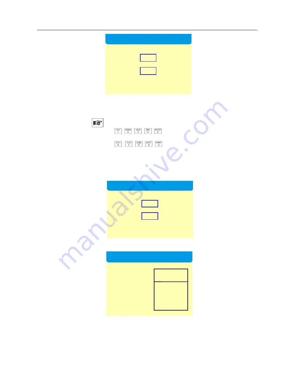
  Click  “OK”  to  enter  the  “Out  2  Setup”  interface  and  you  can  enter  the 

width  and  height  of  the  LED  screen  loaded  in  the  transmitter  card  connected  with 

DVI-OUT2. 


Step 6:

 Click “OK” to return to the “Main Menu” interface and select “Save”. 


Step  7:  Select  “Mode  1”,  click  “OK”  and  it  will  prompt  “Saved  Successfully”. 

That’s all for device debugging. 

Out 2 Setup


 H Size   1024  Step

×1


 V Size   1080 

Press OK to next


Out 1 Setup


 H Size   1024  Step

×1


 V Size   1080 

Press OK to next


Save Mode 


 ★ 【Mode 1】 
      Mode 2 
      Mode 3 
      Mode 4 
      Mode 5 
 

Note 

Summary of Contents for KS800

Page 1: ...Kystar KS800 2K HD Big LED Display Video Processor Multi Window Processor 1 Full Color LED Multi Window Video Processor User Manual ...

Page 2: ...tion and keep it properly for future use 2 In the case of lightning or long term downtime please unplug the power socket 3 This device is not suitable for non professional debugging or operation so please use it under the guidance of professionals 4 Never force anything into this device from its air vent lest device damages or accidents happen 5 This device should not be placed or used near water ...

Page 3: ...creen 12 1 One transmitter card has one frame enabled 12 2 One transmitter card has two frames enabled 14 3 Two transmitter cards have one frame enabled 17 4 Two transmitter cards have two frames enabled 19 Partial debugging 22 1 Single window partial display 22 2 Double window partial display 24 VIII Control menu 26 1 Language options 28 2 Factory Settings 28 3 Technical support 29 4 Output resol...

Page 4: ...ger loss during signal format conversion 3 The LED large screen control system can only capture and display the images at the corresponding pixels on the LED led screen while some users need casual display of partial or complete computer desk pictures freely at the scene 4 With the constant decrease of the LED screen spacing and the constant increase of the on screen pixels the era will no longer ...

Page 5: ...point by point able to be reduced to a pixel 7 Support the motion compensation to eliminate picture tailing 8 Support the noise reduction processing to reduce the noise stains 9 Support HSD video signal input 8 channels SDI optional audio input 4 channels and audio output 1 channel 10 Support the maximum output resolution of 2560 1536 11 Support the keyboard lock function to prevent wrong operatio...

Page 6: ... 3v Sync 75Ω terminal interface HDMI input Number of Inputs 1 Supported Standards HDMI 1 3 EDID 1 3 Signal Level 1Vpp 3dB 0 7V Video 0 3v Sync 75Ω terminal interface VGA DB15 input Number of Inputs 2 Interface form Standard DB15 socket Supported Resolution VGA UXGA Signal Level R G B Hsync Vsync 0 to1Vpp 3dB 0 7V Video 0 3v Sync 75Ω terminal interface Black level 300mV Sync tip 0V DVI Input Number...

Page 7: ...050 60Hz 1920 1080 60Hz 1920 1200 60Hz 1536 1536 60Hz 2560 1536 60Hz Signal level TMDS level 165MHZ bandwidth Auxiliary CE standard certification BS EN 55013 2001 A1 2003 A2 2006 BS EN 61000 3 2 2006 A2 2009 BS EN 6100 3 3 2008 BS EN 55020 2007 BS EN 6006 2002 A1 2006 A11 2008 Computer control RS232 Power supply 85 264V 2A IEC 3 power supply interface Work environment 0 C 45 C Storage environment ...

Page 8: ...Kystar KS800 2K HD Big LED Display Video Processor Multi Window Processor 8 IV Work schematic diagram LED led screen Transmitter card Video processor Desktop Laptop STB Camera DVD ...

Page 9: ... 7 HDMI Key for HD multimedia channel 8 PIP Key for double window shortcut setting 9 MODE User mode call 10 MENU Main Menu 11 OK Enter key 12 ADJUST Key for increase decrease press down and it can act as an Enter key 14 15 VGA Key for analog signal channel 16 DVI Key for digital signal channel 17 SDI Serial digital interface 18 OUT Switching among black screen blue screen and normal 19 PART Partia...

Page 10: ... input interface for laptops etc 4 DVI DVI signal input interface for desktops etc 5 6 VGA VGA signal input interface for laptops etc 7 8 9 CV 1 2 3 Compound signal input interfaces for cameras etc 10 11 DVI OUT1 2 DVI output to connect transmitter cards etc 12 Power port 220V power port 13 14 CARD 1 2 Transmitter card slot able to accommodate transmitter cards with built in 5V power supply line p...

Page 11: ...To facilitate customers flexible and convenient operation the processor can accommodate the transmitter card namely the transmitter card can be installed in the processor and powered on by the processor which thus has eliminated the limitation that the transmitter card must be powered on by a desktop The installation method is detailed as follows Remove the anchorage corner on the transmitter card...

Page 12: ...r card has one frame enabled Step 1 Click on MENU to enter the Main MENU interface Note Turn the knob and you can select different functions click OK to confirm the selected function Step 2 Click Device Mode to enter the interface for device mode options and select Copy Mode Step 3 Click OK to enter the Out Format interface and if the led screen pixels are fewer than 1920 x 1080 select the first i...

Page 13: ...eftward to decrease while rightward to increase with the adjustment step size changed by means of 2 Directly enter the numeric key to complete changes Step 5 Click OK to return to the Main Menu interface and select Save Step 6 Select Mode 1 click OK and it will prompt Saved Successfully That s all for device debugging Save mode Mode 1 Mode 2 Mode 3 Mode 4 Mode 5 Note Out Format Current Format 1920...

Page 14: ...Click OK to enter the Out Format interface and if the led screen pixels are fewer than 1920 x 1080 select the first item Not Change but if the led screen pixels are more than 1920 x 1080 select the second item Change to enter the Out Format interface and then select a resolution larger than the on screen pixels Step 4 Click OK to enter the Panel Para interface and input the actual on screen pixels...

Page 15: ...el and the interface Layout will appear turn the knob to select POP and click OK Note Select PIP click OK and a red square will appear behind PIP which indicates that it has been successfully selected after selected it will not jump to the Main Menu interface automatically and you need to click on MENU to return to the Main Menu interface Step 6 Click the MENU button on the front panel select Scal...

Page 16: ...n entered you do not need to click OK but just click WIN2 to enter the Image 2 Para interface after the Image 2 Para has been entered then click OK Step 8 Click OK to return to the Main Menu interface and then select Save Mode Step 9 Select Mode 1 click OK and it will prompt Saved Successfully That s all for device debugging Image 1 Para H Pos 0 V Pos 0 H Size 0 V Size 0 Image 2 Para H Pos 0 V Pos...

Page 17: ... to enter the Out Format interface and if the led screen pixels are fewer than 1920 x 1080 select the first item Not Change but if the led screen pixels are more than 1920 x 1080 select the second item Change to enter the Out Format interface and then select a resolution larger than the on screen pixels Step 4 Click OK to enter the Out 1 Setup interface and you can enter the width and height of th...

Page 18: ...changes Step 5 Click OK to enter the Out 2 Setup interface and you can enter the width and height of the LED screen loaded in the transmitter card connected with DVI OUT2 Step 6 Click OK to return to the Main Menu interface and select Save Step 7 Select Mode 1 click OK and it will prompt Saved Successfully That s all for device debugging Out 2 Setup H Size 1024 Step 1 V Size 1080 Press OK to next ...

Page 19: ... to enter the Out Format interface and if the led screen pixels are fewer than 1920 x 1080 select the first item Not Change but if the led screen pixels are more than 1920 x 1080 select the second item Change to enter the Out Format interface and then select a resolution larger than the on screen pixels Step 4 Click OK to enter the Out 1 Setup interface and you can enter the width and height of th...

Page 20: ...c key to complete changes Step 5 Click OK to enter the Out 2 Setup interface and you can enter the width and height of the LED screen loaded in the transmitter card connected with DVI OUT2 Step 6 Click OK to return to the Main Menu Click the button PIP on the front panel and the interface Layout will appear turn the knob to select POP and click OK Out 2 Setup H Size 1024 Step 1 V Size 1080 Press O...

Page 21: ...d size of the first image Step 8 Click the WIN2 button on the front panel to enter the Image 2 Para interface and you can enter the location and size respectively of the second image Note After the Image 1 Para has been entered you do not need to click OK but just click WIN2 to enter the Image 2 Para interface after the Image 2 Para has been entered then click OK Step 9 Click OK to return to the M...

Page 22: ...g has been completed if no full screen debugging has been done please complete full screen debugging first Partial debugging includes single or double windows and is not related to the number of transmitter cards Note The following debugging operations are all carried out after the above mentioned full screen debugging has been completed 1 Single window partial display Step 1 click on MENU to ente...

Page 23: ...values as the starting point x starting point y width and height of the LED studio into the horizontal position vertical position horizontal size and vertical size Step 3 Click OK to return to the Main Menu interface and then select Save Step 4 Select Mode 1 click OK and it will prompt whether it is overwritten click on the button to select Overwrite Mode 1 and it will prompt Saved Successfully Th...

Page 24: ...w 2 The numerical value can be changed as follows 1 You can use the knob to adjust it leftward to decrease while rightward to increase with the adjustment step size changed by means of 2 Directly enter the numeric key to complete changes 3 Commonly for partial display we should intercept the LED studio and just enter such numerical values as the starting point x starting point y width and height o...

Page 25: ...al position horizontal size and vertical size respectively Step 4 Click OK to return to the Main Menu interface and then select Save Step 5 Select Mode 1 click OK and it will prompt whether it is overwritten click on the button to select Overwrite Mode 1 and it will prompt Saved Successfully That s all for device debugging Note To switch the first window between Partial Display and Full Display ju...

Page 26: ...rol menu Main menu Options Default I Screen settings Copy Mode Split Mode Monitor Mode II Image parameters Horizontal position 0 Vertical position 0 Horizontal size 1920 Vertical size 1080 III Partial display Horizontal position 0 Vertical position 0 Horizontal size 0 Vertical size 0 IV Save mode Save Mode 1 Save Mode 2 Save Mode 3 Save Mode 4 Save Mode 5 V User mode Mode 1 Mode 2 Mode 3 Mode 4 Mo...

Page 27: ... 60Hz 1920 1080 60Hz 1920x1200 60Hz 2560 1152 60Hz customizable V Output settings Output Port 1 Settings Output Port 2 Settings VI VGA settings Horizontal position Default Vertical position Default Horizontal size Default Vertical size Default VII Brightness settings Brightness 128 Red 128 Green 128 Blue 128 VIII Image static Image static Image active IX Sound settings Mute Output Volume 100 Audio...

Page 28: ...t for the video processor and the user can switch Chinese and English in the Language Settings menu in Advance Menu 2 Factory Settings When too much data is stored in a video processor or set in disorder you can restore its factory settings II Keyboard lock Enabled Disabled III Contrast settings Contrast 128 Red 128 Green 128 Blue 128 IV Switching effects Direct switching Special effects V Schedul...

Page 29: ...you can also adjust the volume 10 Expert settings Here include five functions such as mode shortcut keyboard lock play type play memory and online upgrade When the mode shortcut is enabled the numbers 1 5 on the front panel only correspond to 5 kinds of user modes In order to prevent users incorrect operation the video processor is provided the function of keyboard lock and when the function is en...

Page 30: ...xes video matrixes and other relevant devices Q2 Briefly introduce how to connect the graphics card video processor transmitter card receiver card and LED screen body A Connect the DVI VGA output port of the graphics card to the video processor DVI IN VGA IN The DVI OUT of the video processor outputs to the transmitter card The transmitter card is connected with the terminal receiver card at the b...

Page 31: ... screen display is normal if the graphics card is directly connected with the transmitter card but after a video processor is connected a black screen will appear A See whether the transmitter card green indicator is flashing normally if normal it indicates that the processor has output signal and then the possible reasons may be as follows There s something wrong with the signal source You need t...

Reviews: