Instruction Manual
Earth Resistance/ Earth Resistivity Tester
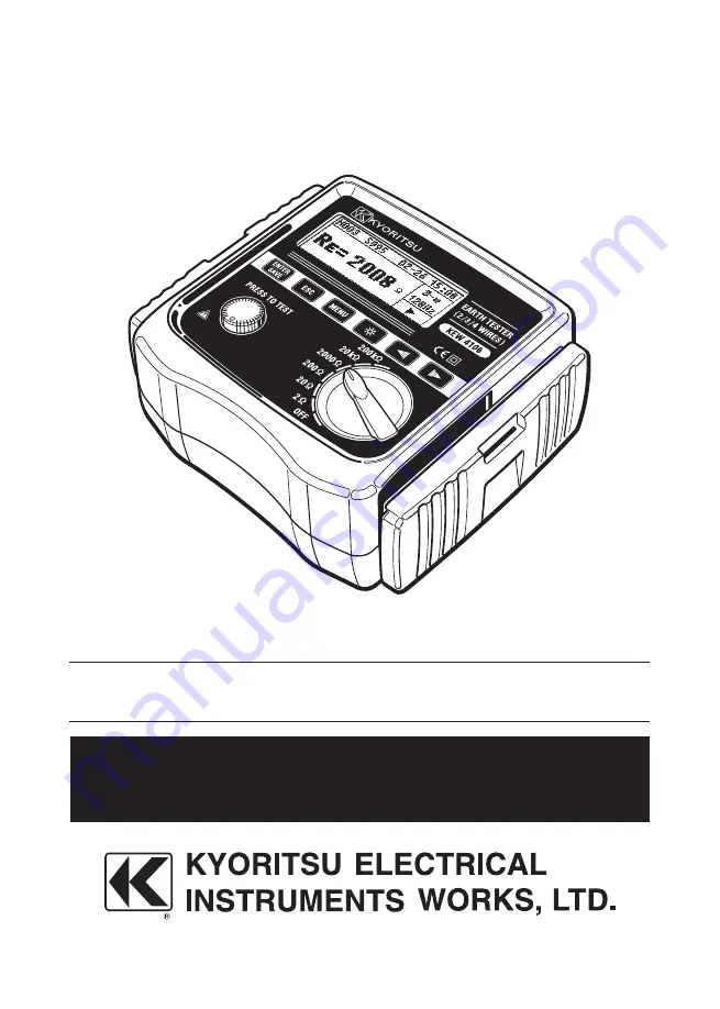
KEW 4106
Page 1: ...Instruction Manual Earth Resistance Earth Resistivity Tester KEW 4106...
Page 2: ......
Page 3: ...Voltage Check 15 8 2 Settings 15 8 2 1 Setting Items 15 8 2 2 Setting for Measurement Method 16 8 2 3 Setting for Measurement Frequency 16 8 2 4 Site location No Setting 17 8 2 5 Setting for the inte...
Page 4: ...all the Measurement Results 34 10 1 How to save the data 34 10 2 How to recall the saved data 35 10 3 How to delete the saved data 35 10 3 1 Delete the data one by one 35 10 3 2 Delete the whole data...
Page 5: ...quick reference whenever necessary The instrument is to be used only in its intended applications Understand and follow all the safety instructions contained in the manual It is essential that the abo...
Page 6: ...e Test Button before connecting the Test Leads Never open the Battery cover during a measurement WARNING Never attempt to make any measurement if any abnormal conditions such as a broken cover or expo...
Page 7: ...teries if the instrument is to be stored and will not be in use for a long period Do not expose the instrument to direct sunlight high temperatures humidity or dew Use a damp cloth with neutral deterg...
Page 8: ...I 300V CAT IV150V To ensure safe operation of measuring instruments IEC 61010 establishes safety standards for various electrical environments categorized as CAT II to CAT IV and called measurement ca...
Page 9: ...t the instrument body from becoming dirty The Cover can be detached and put on the backside of the main body during measurements 2 1 Method of removing the Cover Slide and pull the Cover in the direct...
Page 10: ...to view the test results in dimly areas Can switch frequencies of measuring signal 4 kind of frequencies 94 105 111 128Hz are selectable by hand or automatically Rk Function is available to cancel the...
Page 11: ...03 20 0 01 0 03 20 99 Note 1 2 rdg 5dgt 200 0 1 0 3 209 9 2000 1 3 2099 20k 10 0 03k 20 99k 200k 100 0 3k 209 9k Auxiliary Earth Resistance Rh Rs 8 of Re Rh Rs Earth Resistivity 2 0 1 m 1 m Auto rangi...
Page 12: ...manganese batteries repeating measurements at every 30 sec with a load of 1 at 2 Range Over range Indication OL Auto Power Off automatically powered off when 5 min passes without any Key operation Loc...
Page 13: ...mperature E4 Variation due to series interference voltage E5 Variation due to resistance of the probes and auxiliary earth electrode resistance Range to keep the maximum operating error Measurement ra...
Page 14: ...onnector LCD ENTER SAVE Key ESC Key MENU Key Backlight Key Cursor Key TEST Button Range Switch Earth Terminal E Probe Terminal ES for the Earth Terminal side Probe Terminal S Auxiliary Earth Terminal...
Page 15: ...for voltage measurement The Alligator clips need to be attached and used under CAT III IV test environments and the Flat Test Bars are under CAT II test environment Precision Measurement Test Leads MO...
Page 16: ...spikes in total Cord Reel MODEL8200 04 x 1set 4reels in total for MODEL7229A Optical Adaptor MODEL8212USB x 1 set Communication Software CD ROM KEW Report x 1 pce SizeAA Manganese battery R6P x 8 pcs...
Page 17: ...for Rk can be made at 20 or lower Setting for Rk can be made only at 2w 3w 4w measurements Ust is Regulated value or more Rh and Rs values exceed the allowable range Correct results might not be obta...
Page 18: ...ode This unit outputs test voltage Um to generate AC current I Earth resistance value Rx is determined by the AC current I and potential difference V See Fig 7 2 Principle of Earth Resistivity Measure...
Page 19: ...Battery Mark appears on the LCD 8 2 Settings 8 2 1 Setting Items This instrument starts with Measurement mode Fig 6 Main Screen when it is powered on while the Range Switch has been set to the positio...
Page 20: ...and press the Key to proceed to the Wiring Setting Screen Fig 9 Select the appropriate Wiring System with the Cursor Key and press the Key Then the CONFIG SETTING Screen with the selected Wiring Syste...
Page 21: ...Fig 13 Select any digit to be changed with the Cursor Key and press the Key Then the selected digit is highlighted and ready to be changed Fig 14 Press the Right Cursor Key to increase numbers and th...
Page 22: ...change numbers quickly Press the Key to confirm a number Repeat this procedure to change the other digits Press the Key when settings are done Then the CONFIG SETTING Screen Fig 18 with a new interval...
Page 23: ...igit is highlighted and ready to be changed Fig 21 The clock is 24 hour display Press the Right Cursor Key to increase numbers and the Left Cursor Key to reduce numbers Keep the Cursor Key pressed dow...
Page 24: ...change numbers quickly Press the Key to confirm a number Repeat this procedure to change the other digits Pressing the Key when settings are done returns to the Time Date Setting Screen Fig 25 Press...
Page 25: ...nd press the Key to display the Rk Setting Screen Fig 26 Press the Test Button to measure Rk The measured results will not be saved until the Button is pressed The CONFIG SETTING Screen Fig 27 is disp...
Page 26: ...measurements 8 3 Backlight To facilitate working in dimly lit situations or in night time a backlight function is provided which illuminates the LCD Press the Key to operate this function The backligh...
Page 27: ...Measurement This instrument can measure and display the auxiliary earth resistances Rh Rs When the Rh or Rs value is more than Regulated value or 50k a warning message or appear The LCD shows Rh OL or...
Page 28: ...the values of single earthed system are obtained since these earth resistance can be considered that they are connected in parallel Let s regard earth resistance under test as Rx and the other earth r...
Page 29: ...g connectors on the instrument 2 Select the 2 or 20 Range 3 Engage 3 Alligator clips to short circuit all of them 4 Save the Rk values with reference to 8 2 7 Setting for the residual resistance on th...
Page 30: ...rn to the Main Screen Note The readings may not correct when the auxiliary earth resistance is too high Stick the Auxiliary Earth Spikes S P and H C in the moist part of the soil If a message or appea...
Page 31: ...ODEL 7229A The ES Terminal is also used with the other terminals used at the 3 wire Precise measurements In this case more precise results can be obtained because auxiliary earth resistances of the me...
Page 32: ...nection of Auxiliary Earth Spikes and Test Leads Stick the Auxiliary Earth Spikes S P and H C into the ground deeply They should be aligned at an interval of 5 10m from the earthed equipment under tes...
Page 33: ...cuited and the input impedance will be reduced The residual current circuit breaker may operate when making measurements of the voltage in the circuit with the breaker ELCBs may trip when performing s...
Page 34: ...break in Test Leads or burnout of Fuse is suspected when the LCD shows Rk OL while 4 Test Leads are being shorted 3 Connection Connect the Test Leads as shown in Fig 40 Note When the supplied Simplif...
Page 35: ...they should be separated Making a setting of the interval between Auxiliary Earth Spikes first and measuring the earth resistances with the 4 Auxiliary Earth Spikes stuck into the ground at even inte...
Page 36: ...ted to the E ES S P and H C Terminals on the instrument to the Auxiliary Earth Spikes from the closest to the farthest in this order Fig 41 3 Setting of the Interval between Auxiliary Earth Spikes The...
Page 37: ...scribes the detailed setting procedure Note The depth should be 5 or less of the interval between the spikes If the Spikes stuck too deep it may result in inaccurate earth resistivity measurement Note...
Page 38: ...measured values are saved Fig 46 Press the Key to return to the Main Screen Note Pressing the TEST Button again initiates another measurement Note Data cannot be saved while the Low Battery Mark is di...
Page 39: ...on Press the Cursor Keys or Key and select Data No Keep a Cursor Key pressed down to alter the number quickly Note When no data has been saved in the memory following message is displayed on the LCD F...
Page 40: ...een is displayed with the next data Note Number of the saved data is decreased after deleting some data but the Data No will not be changed So the last Memory No may become bigger than the No showing...
Page 41: ...d according to following sequence The special software KEW Report should be installed beforehand 1 Connect Model 8212 USB to the USB terminal of a PC 2 Disconnect the Test Leads from the instrument an...
Page 42: ...n disposing the old batteries please follow your local regulations 11 1 Battery Replacement 1 Set the Range Switch to the OFF position and disconnect the Test Leads from the instrument 2 Unscrew the B...
Page 43: ...39 SPARE FUSE SCREW FUSE BATTERY Fig 61...
Page 44: ...strap Assembly By hanging the instrument around the neck both hands will be let free for testing Pass the Shoulder strap down through Adjust the strap for length and the buckle from the top Fig 62 sec...
Page 45: ...in correct polarity Refer to 11 Battery and Fuse Replacement Batteries are not installed in the instrument at the time of shipment Incapable of setting Rk Fig 64 65 Selectable Rk values at 2 and 20 R...
Page 46: ...urement Check the condition of the Earth Spikes stuck into the ground Refer to 9 1 Earth Resistance Measurement The LCD reads OL or Rg OL at earth resistivity measurements Re measurements Fig 72 The R...
Page 47: ...l the Measurement Results Incapable of transferring data to PC Instrument is powered on MODEL 8212 USB Cable and the PC are connected properly MODEL 8212 USB Cable is properly connected to the Communi...
Page 48: ...2 14 92 1962C DISTRIBUTOR Kyoritsu reserves the rights to change specifications or designs described in this manual without notice and without obligations...