2H4
2-1-9
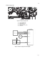
2-1-5 Transfer/separation section
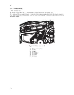
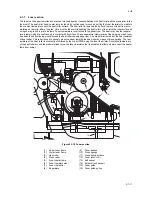
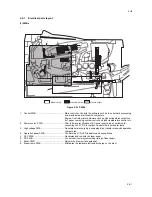
The transfer/separation section consists of the transfer roller, discharger brush and paper chute guide. A high voltage gen-
erated by the high voltage PWB is applied to the transfer roller for transfer charging. Paper after transfer is separated from
the drum.
Figure 2-1-14 Transfer/separation section
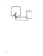
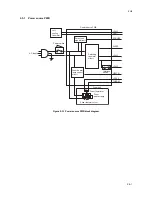
Figure 2-1-15 Transfer/separation section block diagram
1
4
2
3
5
(1)
Transfer roller
(2)
Transfer bushes
(3)
Discharger brush
(4)
DC brush holder
(5)
Paper chute guide
Transfer
roller
High voltage
PWB
Transfer bias
Discharger
brush
T
S
Separation bias
Summary of Contents for ECOSYS FS-1350DN
Page 1: ...SERVICE MANUAL Published in October 2008 842H4010 2H4SM060 First Edition FS 1350DN ...
Page 3: ...Revision history Revision Date Replaced pages Remarks ...
Page 4: ...This page is intentionally left blank ...
Page 10: ...This page is intentionally left blank ...
Page 18: ...2H4 1 1 6 This page is intentionally left blank ...
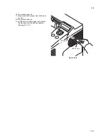
Page 21: ...2H4 1 2 3 1 Removing the tapes Procedure 1 Remove three tapes Figure 1 2 3 Tape Tape Tape ...
Page 24: ...2H4 1 2 6 This page is intentionally left blank ...
Page 57: ...2H4 1 5 5 5 Unhook seven hooks and then remove the left cover Figure 1 5 6 Left cover Hooks ...
Page 106: ...2H4 2 1 16 This page is intentionally left blank ...
Page 110: ...2H4 2 2 4 This page is intentionally left blank ...
Page 118: ...2H4 2 3 8 This page is intentionally left blank ...
Page 121: ......
Page 122: ......

