Kyocera Mita KM-1505 Service Manual Download Page 46

2BT

1-4-15

Maintenance

Description

item No.

U093

Setting the exposure density gradient

Description
Changes the exposure density gradient in manual density mode, depending on respective image modes (text,
text and photo, photo).

Purpose
To set how the image density is altered by a change of one step in the manual density adjustment. Also used to
make copy image darker or lighter.

Start

1. Press the start key. A selection item appears.
2. Select the image mode to be adjusted by lighting image mode LEDs using the image mode selection key.
3. Press the start key. The machine enters the setting mode.
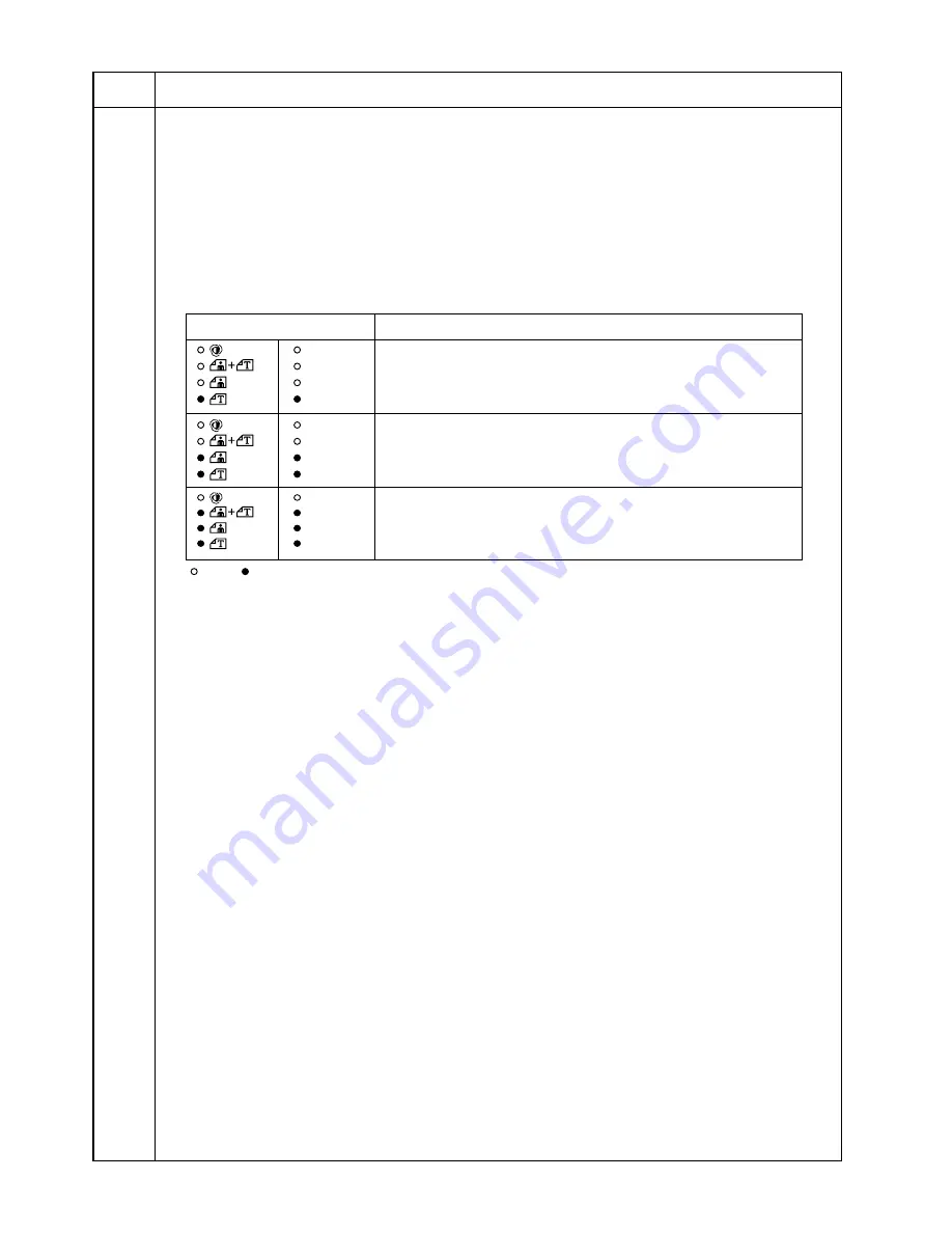
Image mode LEDs

Description

Photo

Text

Text & Photo

AutoExp.

Density in text mode

Photo

Text

Text & Photo

AutoExp.

Density in text and photo mode

Photo

Text

Text & Photo

AutoExp.

Density in photo mode

: Off, 

: On

Summary of Contents for KM-1505

Page 1: ...SERVICE MANUAL Published in June 01 2BT70760 KM 1505...

Page 2: ...URER DISPOSE OF USED BATTERIES ACCORDING TO THE MANUFACTURER S INSTRUCTIONS ATTENTION IL Y A DANGER D EXPLOSION S IL Y A REMPLACEMENT INCORRECT DE LA BATTERIE REMPLACER UNIQUEMENT AVEC UNE BATTERIE DU...

Page 3: ...sonnel to ensure the safety of their customers their machines as well as themselves during maintenance activities Service personnel are advised to read this booklet carefully to familiarize themselves...

Page 4: ...mpliance with warning messages using this symbol WARNING Serious bodily injury or death may result from insufficient attention to or incorrect compliance with warning messages using this symbol CAUTIO...

Page 5: ...or dusty place This may cause fire or electric shock Do not install the copier near a radiator heater other heat source or near flammable material This may cause fire Allow sufficient space around th...

Page 6: ...clean Dirt on them can cause abnormally high temperatures Do not remove the ozone filter if any from the copier except for routine replacement 2 Precautions for Maintenance WARNING Always remove the...

Page 7: ...t all the caution labels that should be present on the machine according to the instruction handbook are clean and not peeling Replace with new ones if necessary Handle greases and solvents with care...

Page 8: ...5 Troubleshooting 1 5 1 Paper misfeed detection 1 5 1 1 Paper misfeed indication 1 5 1 2 Paper misfeed detection conditions 1 5 2 3 Paper misfeeds 1 5 5 1 5 2 Self diagnosis 1 5 7 1 Self diagnostic fu...

Page 9: ...d paper feed 1 5 22 4 The scanner does not travel 1 5 22 5 Multiple sheets of paper are fed at one time 1 5 22 6 Paper jams 1 5 22 7 Toner drops on the paper conveying path 1 5 22 8 Abnormal noise is...

Page 10: ...djustment free variable resistors VR 1 7 4 2 1 Mechanical construction 2 1 1 Paper feed section 2 1 1 2 1 2 Main charging section 2 1 3 2 1 3 Optical section 2 1 5 1 Original scanning 2 1 6 2 Image pr...

Page 11: ...ontinuous copying 1 99 sheets Photoconductor OPC drum diameter 30 mm Charging system Single positive corona charging Exposure light source Semiconductor laser Developing system Dry reverse developing...

Page 12: ...7 Support guide 8 Toner container 9 Waste toner tank 0 Cleaning shaft Front cover Main switch Copy storage section Drawer Platen Original size scales Length guide Width guide Width adjustment lever L...

Page 13: ...pies Zoom key 5 Number of Copies Zoom key 6 Zoom Input Enter key 7 Copy quantity magnification display 8 Add Toner indicator 9 Paper Select key 0 Drawer indicator Multi bypass indicator Misfeed indica...

Page 14: ...r feed section 2 Main charging section 3 Optical section 4 Developing section 5 Transfer and sparation section 6 Cleaning section 7 Charge erasing section 8 Fixing section Figure 1 1 3 Machine cross s...

Page 15: ...ar 7 Registration clutch gear 8 Gear 32 18 9 Paper feed clutch gear 0 Gear 97 25 Drum drive gear 53 Gear 40 45 Gear 41 Gear 28 20 Gear 26 20 Fixing idle gear 44 Gear 25 Heat roller gear Figure 1 1 4 1...

Page 16: ...1 1 6 2 Drive system 2 scanner motor drive train Figure 1 1 5 1 Scanner motor gear 2 Scanner drive gear 27 13 3 Scanner belt 4 Gear Z23 5 Idle gear 21 6 Gear Z30 As viewed from machine rear 1 2 3 6 5...

Page 17: ...and 32 5 C 90 5 F and at a relative humidity not higher than 85 RH Avoid abrupt changes in temperature and humidity Avoid exposure to any substance which is harmful to or may affect the quality of the...

Page 18: ...vibration Choose a surface capable of supporting the weight of the machine Place the machine on a level surface maximum allowance inclination 1 Avoid air borne substances that may adversely affect th...

Page 19: ...e Unpack Remove the tapes Adjust the fixing pressure Remove the pad inside the machine Install a waste toner tank Connect the power cord Load paper Make test copies Start Remove the pins holding light...

Page 20: ...ads 4 Stay 5 Outer case 6 Bottom pads 7 Tray spacer 8 Machine cover 9 Scanner pin tag 0 Fixing lever tags Waste toner tank spacer Bar code labels Drawer spacer Front drawer spacer Sheet Instruction ha...

Page 21: ...1 3 3 2BT 1 Remove the 11 tapes 2 Open the bypass tray and paper conveying cover and then remove the two tapes Remove the tapes Figure 1 3 2 Figure 1 3 3 Tapes...

Page 22: ...e sure to load paper after the main switch is turned on and copying is enabled Loading paper before turning the main switch on may cause paper jams 5 Open the original cover and remove the sheet on th...

Page 23: ...cover The storing locations of the pins are marked inside the front cover Caution Be sure to refit the pins whenever the copier is moved 8 Remove the pad This step is not necessary for metric specifi...

Page 24: ...and tap the top 15 times Then hold the container horizontally and shake it from side to side 10 times 10 Insert the toner container into the copier as far as it will go and then slide it to the right...

Page 25: ...ers and drawers 12 Connect the power cord and turn the main switch on Caution Never turn the power off or open covers while the copier is driving Doing so may cause printing problems or contaminate th...

Page 26: ...e required paper width 16 While squeezing the presses on the sides remove the length guide and then insert it into the holes of the required paper length Store the length guide in the space shown in t...

Page 27: ...gth and width guides securely contact the paper If there is a gap adjust the position of the length or width guide to close it Load paper all at once and do not add paper until all sheets are used up...

Page 28: ...54 U255 U256 U258 U260 U348 Turning auto start function on off Setting auto clear time Turning auto preheat energy saver function on off Switching copy operation at toner empty detectionempty detectio...

Page 29: ...copier administrator In this copier management mode default settings can be changed 1 Executing a copier management item Press both of the copy exposure adjustment keys for 3 s Start Executing a defau...

Page 30: ...e image mode 1 Select F07 and press the enter key 2 Select the setting and press the enter key Setting range 1 to 5 Drawer paper size Sets the size of paper loaded in the drawer 1 Select F08 and press...

Page 31: ...age requesting the user to replace the toner container is printed when the toner is used up 1 Select F19 and press the enter key 2 Select on or off and press the enter key Setting range 1 on 2 off Pap...

Page 32: ...ted using the copy exposure adjustment keys or the zoom keys Press the start key Press the stop reset key The maintenance item is run Press the stop reset key Enter 001 using the copy exposure adjustm...

Page 33: ...rection auxiliary scanning direction 0 U066 Adjusting the leading edge registration for scanning an original on the 0 contact glass U067 Adjusting the center line for scanning an original on the conta...

Page 34: ...f On U255 Setting auto clear time 90 U256 Turning auto preheat energy saver function on off On U258 Switching copy operation at toner empty detection Single mode 70 U260 Changing the copy count timing...

Page 35: ...ected item appears Completion Press the stop reset key while a selection item is displayed The indication for selecting a maintenance item No appears U001 Exiting the maintenance mode Description Exit...

Page 36: ...is simulated without paper under the set conditions When operation is complete the selected item appears 7 To stop continuous operation press the stop reset key Completion Press the stop reset key at...

Page 37: ...destination setting When initialization is complete the machine automatically returns to the same status as when the main switch is turned on Completion Press the stop reset key The indication for sel...

Page 38: ...rn each switch on and off manually to check the status While each switch is turned on a segment of the 7 segment display lights Segments of the 7 segment display and the switches correspond as follows...

Page 39: ...4 Adjusting the print start timing Adjustment See pages 1 6 8 and 9 U042 Setting the LSU type Description Sets the type of the LSU installed in the copier Purpose Used when replacing the LSU Method 1...

Page 40: ...lygon motor speed adjustment unit Increasing the setting makes the image longer in the main scanning direction and shorter in the auxiliary scanning direction decreasing the setting makes the image sh...

Page 41: ...check the exposure lamp Method 1 Press the start key on appears 2 Press the start key The exposure lamp lights 3 To turn the exposure lamp off press the stop reset key Completion Press the stop reset...

Page 42: ...start key 2 Select the item to be changed by lighting a copy exposure indicator using the copy exposure adjustment keys 3 Change the setting using the zoom keys Copy exposure indicator Operating condi...

Page 43: ...reduced 2 Press the start key The value is set The indication for selecting a maintenance item No appears Completion To exit this maintenance item without changing the current setting press the stop...

Page 44: ...re shading and displays the result oFF Performs scanning after shading and displays the result 3 Press the start key Scanning is performed under the selected conditions and the result is displayed 4 C...

Page 45: ...lly by running the corresponding maintenance items Completion Press the stop reset key after auto adjustment is complete The indication for selecting a maintenance item No appears If the stop reset ke...

Page 46: ...in the manual density adjustment Also used to make copy image darker or lighter Start 1 Press the start key A selection item appears 2 Select the image mode to be adjusted by lighting image mode LEDs...

Page 47: ...kes the change in density larger and decreasing it makes the change smaller Image density Density adjustment Dark Light Light Center Dark Density adjustment range Special area Setting 0 Setting 3 Dens...

Page 48: ...ustment keys Display copy exposure indicator Description on1 exp 1 Turning the main charger on on2 exp 3 Turning the main charger on and the laser scanner unit on and off 2 Press the start key The sel...

Page 49: ...kes the bias lower and the image lighter 3 Press the start key The value is set Setting the transfer voltage 1 Select the item to be adjusted by lighting a copy exposure indicator using the copy expos...

Page 50: ...reference when correcting the main charger potential output Purpose To check the drum status Also used to clear the count after replacing the drum during regular maintenance Since the count was cleare...

Page 51: ...eset key The indication for selecting a maintenance item No appears U130 Initial setting for the developer Description Automatically sets the toner sensor control voltage and toner feed start level fo...

Page 52: ...requently Method 1 Press the start key 2 Press the start key Operation starts and the current data is displayed Toner is replenished until the toner sensor output value reaches the toner feed start le...

Page 53: ...ed by the difference from the toner feed start level Purpose To check the toner feed start level and toner empty level Method 1 Press the start key 2 Select the item by lighting a copy exposure indica...

Page 54: ...o exit this maintenance item without changing the time press the stop reset key The indication for selecting a maintenance item No appears U158 Checking clearing the developing count Description Displ...

Page 55: ...set key The indication for selecting a maintenance item No appears U162 Stabilizing fixing forcibly Description Stops the stabilization fixing drive forcibly regardless of fixing temperature Purpose T...

Page 56: ...s the start key The fixing heater turns on for 1 s and then turns off Completion Press the stop reset key when fixing heater is off The indication for selecting a maintenance item No appears U199 Chec...

Page 57: ...he LEDs light for up to 10 seconds 5 When the LEDs go off press the start key All the LEDs light for 10 seconds again Completion Press the stop reset key The indication for selecting a maintenance ite...

Page 58: ...ement or initialization Method Press the start key Setting 1 Select the destination using the zoom keys Display Description JPn Metric Japan specifications Inc Inch North America specifications EUP Me...

Page 59: ...he problem Method Press the start key Setting 1 Select either on or oFF using the zoom keys Display Description on Auto start function on oFF Auto start function off Initial setting on 2 Press the sta...

Page 60: ...top reset key The indication for selecting a maintenance item No appears U256 Turning auto preheat energy saver function on off Description Selects if the auto preheat energy saver function is turned...

Page 61: ...empty detection Off On Setting copy operation at toner empty detection between single and continuous copying 1 Select single or continuous copying using the zoom keys Display Description Sin Enables o...

Page 62: ...paper jam occurs frequently in the paper conveying or fixing sections when the number of copies is counted before the paper reaches those sections copying is charged without a copy being made To prev...

Page 63: ...osure Paper size Setting range Initial indicator setting Exp 1 lit A4R 0 0 to 3 0 1 0 Exp 3 lit B5R 0 0 to 3 0 0 7 Exp 5 lit A5R 0 0 to 3 0 0 5 Exp 1 flashing B6R 0 0 to 3 0 0 4 Exp 3 flashing A6R 0 0...

Page 64: ...density range using the zoom keys Display Description SPC special area 5 steps enlargement mode nrL normal 3 steps Initial setting Normal 2 Press the start key The setting is set and the indication fo...

Page 65: ...Copy exposure Copy quantity display count value indicator 1 Photo Text Text Photo AutoExp Exp 1 First 3 digits of bypass copy count Exp 3 Last 3 digits of bypass copy count Exp 5 Clearing the count CL...

Page 66: ...ared Completion Press the stop reset key The indication for selecting a maintenance item No appears U904 Checking clearing the service call counts Description Displays or clears the service call code...

Page 67: ...n Selects whether to read out the backup data on the main PCB to the NVRAM on the memory tool PCB or to write backup data on the NVRAM on the memory tool PCB to the main PCB When the memory is initial...

Page 68: ...uantity display by lighting a copy exposure indicator using the copy exposure adjustment keys Copy exposure indicator Copy quantity display Exp 1 First 3 digits of the lamp on time minutes Exp 3 Last...

Page 69: ...attern Method 1 Press the start key 2 Select the VTC PG pattern to be output using the copy exposure adjustment keys Display PG pattern to be output Purpose 0 Center line adjustment 1 Lateral squarene...

Page 70: ...exposure indicator Description Setting range Exp 1 Bit 16 to bit 23 of the address 00 to FF Exp 3 Bit 8 to bit 15 of the address 00 to FF Exp 5 Bit 0 to bit 7 of the address 00 to FF 2 Enter the addre...

Page 71: ...an be reset by opening and closing the respective covers to turn safety switch off and on 1 Misfeed in paper feed section 2 Misfeed in paper conveying section Figure 1 5 1 Table 1 5 1 Jam code Content...

Page 72: ...2BT 1 5 2 2 Paper misfeed detection conditions Figure 1 5 2 RSW ESW...

Page 73: ...ay The registration switch RSW does not turn on within 1390 ms of the bypass paper feed clutch BYPPFCL turning on BYPPFCL OFF ON OFF ON RSW 1390 ms Timing chart 1 5 2 Multiple sheets in copier paper f...

Page 74: ...section jam code 50 The eject switch ESW does not turn off within 2809 ms of the registration switch RSW turning off RSW OFF ON OFF ON ESW 2809 ms Timing chart 1 5 6 5 Misfeed in registration section...

Page 75: ...t and left registration rollers contact each other Check visually and remove any found With 5 V DC present at CN3 14 on the main PCB check if CN3 13 on the main PCB remains low when the registration s...

Page 76: ...or is broken With 5 V DC present at CN3 14 on the main PCB check if CN3 13 on the main PCB remains low when the registration switch is turned on and off If it does replace the registration switch Chec...

Page 77: ...e backup RAM Poor contact of the connector terminals Defective exposure lamp Defective main PCB or inverter PCB Incorrect shading position CCD PCB output problem Poor contact of the connector terminal...

Page 78: ...ctive LSU Defective main PCB Poor contact of the high voltage transformer PCB connector terminals Defective high voltage transformer PCB Leakage during main charging Check the connection of connector...

Page 79: ...ixing unit thermostat triggered Fixing heater installed incorrectly Broken fixing heater wire Poor contact in the fixing unit thermistor connector terminals Broken fixing unit thermistor wire Fixing u...

Page 80: ...f the toner sensor connector terminals Developer problem Poor contact of the humidity sensor PCB connector terminals Defective external temperature thermistor Poor contact of the humidity sensor PCB c...

Page 81: ...ly See page 1 5 14 8 One side of the copy image is darker than the other See page 1 5 14 9 Black dots appear on the image See page 1 5 15 10 Image is blurred See page 1 5 15 11 The leading edge of the...

Page 82: ...fective high voltage transformer PCB 2 Exposure lamp fails to light A The connector terminals of the exposure lamp make poor contact B Defective inverter PCB C Defective main PCB 2 No image appears en...

Page 83: ...developer 3 Dirty or deteriorated drum Causes 1 Deteriorated developer Causes Check procedures corrective measures 1 Deteriorated developer Check the number of copies made with the current developer I...

Page 84: ...n charger wire 2 Defective exposure lamp Causes Check procedures corrective measures 1 Flawed drum 2 Dirty developing section 3 Leaking main charger housing 7 A black line ap pears laterally Causes 1...

Page 85: ...2 Dirty contact glass 3 Deformed or worn cleaning blade Causes 1 Scanner moves erratically 2 Deformed press roller 3 Paper conveying section drive problem Causes Check procedures corrective measures 1...

Page 86: ...perates incorrectly replace it 14 Offset occurs 13 Paper creases Causes 1 Paper curled 2 Paper damp 3 Defective pressure springs Causes Check procedures corrective measures 1 Paper curled Check the pa...

Page 87: ...ck procedures corrective measures 1 Paper damp Check the paper storage conditions 2 Paper creased Replace the paper 3 Drum condensation Clean the drum 4 Flawed drum Replace the drum see page 1 6 29 16...

Page 88: ...e Check if CN6 10 on the main PCB goes low when maintenance item U030 is run If not replace the main PCB Check if developing bias is output when there is no problem with the main PCB while maintenance...

Page 89: ...replace the cord Check for continuity across the contacts If none replace the main switch Check for continuity If none remove the cause of blowing and replace the fuse Check for continuity across the...

Page 90: ...in PCB Defective high voltage transformer PCB Check for continuity across the coil If none replace the paper feed clutch Reinsert the connector Also check for continuity within the connector cable If...

Page 91: ...egistration switch or eject switch Defective registration switch Defective eject switch Poor contact in the connector terminals of safety switch Defective safety switch Wiring is broken shorted or mak...

Page 92: ...ly curled Deformed guides along the paper conveying path Check if the contact between the right and left registration rollers is correct Check if the press roller is extremely dirty or deformed Check...

Page 93: ...nly the specified parts to replace the fixing unit thermostat Never substitute electric wires as the copier may be seriously damaged Do not perform aging without the waste toner tank installed during...

Page 94: ...ntenance item is run Press the stop reset key Enter 001 using the copy exposure adjustment keys or the zoom keys and press the start key End Entering the maintenance mode Selecting a maintenance item...

Page 95: ...move the printer cover and rear cover Pull out the drawer 2 Remove the four screws and then detach the high voltage transfer PCB Figure 1 6 1 3 Remove the stop ring and then the paper feed clutch Figu...

Page 96: ...the paper feed pulleys and then the pulleys 7 Replace the paper feed pulleys and refit all the removed parts Before returning the drawer turn the main switch on When refitting the paper feed clutch th...

Page 97: ...ter cover rear cover and left cover 2 Remove the image formation unit see page 1 6 27 3 Remove the fixing unit see page 1 6 34 4 Remove the screw and then the fulcrum pin Figure 1 6 6 5 Remove the pap...

Page 98: ...holding the bypass paper feed shaft unit and then the unit Figure 1 6 10 9 Remove the grounding plate bushing and stop ring and then the bypass paper feed pulley Figure 1 6 11 Bypass paper feed clutc...

Page 99: ...ay clutch is machine rear When refitting the bypass paper feed shaft unit check that the hole in the grounding plate is inserted over the projection under the bypass lift plate When refitting the pape...

Page 100: ...ing 0 Changing the value by 1 moves the leading edge by 1 0 mm Press the start key to output a test pattern Exp 1 lit Leading edge registration from the drawer Exp 3 lit Leading edge registration from...

Page 101: ...center line by 1 mm Select the item to be adjusted using the copy exposure adjustment keys Exp 5 lit Center line from the drawer Exp 1 flashing Center line from the bypass tray Press the size select k...

Page 102: ...10 2 5 0 5 mm Printer trailing edge margin 5 10 4 5 0 5 mm Printer trailing edge margin of non standard size from the drawer 0 400 214 1 msec Printer trailing edge margin of non standard size from the...

Page 103: ...larger the amount of slack the smaller the value the smaller the amount of slack The new setting is stored Select the item to be adjusted using the copy exposure adjustment keys Is the leading edge of...

Page 104: ...s follows Procedure 1 Remove the printer cover and right cover and then the contact glass Figure 1 6 17 2 Move the mirror 1 frame to the cutouts of the machine 3 Detach the exposure lamp connector fro...

Page 105: ...2BT 1 6 13 4 Remove the two screws holding the exposure lamp and then the lamp 5 Replace the exposure lamp and refit all the removed parts Figure 1 6 19 Exposure lamp...

Page 106: ...the mirror 1 frame to the cutouts of the machine 3 Detach the inverter wire from the inverter PCB Figure 1 6 20 4 Remove the screw holding each of the front and rear wire retainers 5 Remove the mirror...

Page 107: ...ws holding the motor retainer grounding plate and then the plate Remove the four screws holding the scanner motor unit and then the unit Figure 1 6 23 2 Remove the screw and the gear Figure 1 6 24 3 R...

Page 108: ...the scanner wire drum shaft to the scanner unit Make sure that the locating balls point downward Figure 1 6 26 6 Insert the two frame securing tools into the positioning holes at the front and rear of...

Page 109: ...low to above 3 10 Loop the scanner wires around the inner grooves in the pulleys on the mirror 2 frame winding from above to below 4 11 Wind the scanner wires around the grooves in the scanner wire gu...

Page 110: ...he front cover and remove the waste toner tank and toner container 2 Remove the printer cover and right cover 3 Detach the two connector of the operation unit Figure 1 6 30 4 Remove the two screws hol...

Page 111: ...connector that is covered with a sponge remove the sponge first 7 Replace the laser scanner unit and refit all the removed parts Fit the sponge packing with the new scanner unit 8 Run the maintenance...

Page 112: ...the shield cover 3 Detaach connectors CN16 and CN17 on the main PCB Figure 1 6 34 4 Remove the ISU cable plate 5 Remove the four screws holding the ISU cover and then the cover Figure 1 6 35 6 Remove...

Page 113: ...ut a VTC PG2 pattern in maintenance item U993 to use as the original for the adjustment Procedure Yes No Press the start key and make a test copy at 100 magnification Start Remove the contact glass Lo...

Page 114: ...inal Copy example Copy example 2 Figure 1 6 39 Enter maintenance mode Enter 065 using the copy exposure adjustment keys or zoom keys Yes No Start End Press the size select key and the machine enters t...

Page 115: ...copy example 2 decrease the value using the zoom key Press the start key The new setting is stored Press the start key Select Exp 3 auxiliary scanning direction using the copy exposure adjustment key...

Page 116: ...intenance mode Enter 066 using the copy exposure adjustment keys or zoom keys Press the start key Press the size select key and the machine enters the test copy mode Place an original and press the st...

Page 117: ...keys or zoom keys Press the start key Press the size select key and the machine enters the test copy mode Place an original and press the start key to make a test copy Is the scanner center line corre...

Page 118: ...tenance mode Enter 403 using the copy exposure adjustment keys or zoom keys Press the start key Exp 1 lit Scanner left margin Exp 3 lit Scanner leading edge margin Exp 5 lit Scanner right margin Exp 1...

Page 119: ...bypass tray and paper conveying unit 2 Remove the waste toner tank and toner container 3 Remove the two screws holding the waste toner tank cover and then the cover 4 Remove the screw holding the dev...

Page 120: ...Prucedure 1 Remove the image formation unit see page 1 6 27 2 Remove the screw holding the main charger assemby and then the assembly 3 Replace the main charger unit and refit all the removed parts W...

Page 121: ...and never touch the drum surface After removing the drum keep it in the drum case or storage bag to protect the surface from light Prucedure 1 Remove the image formation unit see page 1 6 27 2 Remove...

Page 122: ...n the new drum flange Securely insert the drum shaft as far as it will go When turning the drum shaft turn it in the direction indicated by the arrow marked on the image formation unit frame Rotate th...

Page 123: ...g blade Figure 1 6 51 5 Replace the cleaning blade and refit all the removed parts Apply toner or white powder to the edge of the new cleaning blade After fitting the cleaning blade slide it to the ri...

Page 124: ...nd refit all the removed parts When disposing of the developer tilt the image formation unit in the direction of A shown in the diagram and rotate the developing spiral gear Never turn the magnet roll...

Page 125: ...assembly Procedure 1 Open the bypass tray and paper conveying unit 2 Remove the transfer roller assembly Caution Remove the transfer roller assembly carefully to prevent the residual toner in the tra...

Page 126: ...nd detach the three connector and then remove the fixing unit Figure 1 6 55 2 Detaching and refitting the fixing unit thermistor Follow the procedure below to replace the fixing unit thermistor Proced...

Page 127: ...the screw holding the fixing unit front cover and then the cover Figure 1 6 57 3 Remove the two screws and detach the fixing heater wire from the fixing thrmostat Figure 1 6 58 4 Remove the screw hol...

Page 128: ...6 5 Pull out the fixing heater from the fixing unit 6 Replace the fixing heater and refit all the removed parts Do not touch the glass surfaces of the fixing heater with bare hands Figure 1 6 60 Fixin...

Page 129: ...ve the screw holding the fixing heater rear retainer and then the retainer Figure 1 6 61 4 Remove the gear 5 Remove the two screws and detach the upper fixing unit Figure 1 6 62 6 Remove the springs f...

Page 130: ...shings and then remove the heat roller 4 Replace the heat roller and refit all the removed parts Figure 1 6 64 6 Detaching and refitting the press roller Follow the procedure below to replace the pres...

Page 131: ...ixing pressure release levers further Figure 1 6 66 6 Remove each of two bearings and fixing pressure release levers and then remove the press roller 7 Replace the press roller and refit all the remov...

Page 132: ...moving the printer cover remove the 6 screws of machine shield cover And then remove the upper shield cover lower shield cover and shield cover 3 Fit the NVRAM to the memory tool PCB Caution After fit...

Page 133: ...on for 1 s off for 1 s for approximately 10 seconds and the machine data on the SRAM of the main PCB will be backed up on the NVRAM 6 When flashing LED1 green on the memory tool PCB remains lit backin...

Page 134: ...ert the memory tool PCB into the copier and connect its CN1 to CN19 on the main PCB Note Insert the memory tool PCB along the upper and lower guides 6 Insert the power plug and turn the main switch on...

Page 135: ...justment free variable resistors VR The variable resistors listed below are set at the factory prior to shipping and cannot be adjusted in the field High voltage transformer PCB VR101 VR102 VR201 VR30...

Page 136: ...n hold up to 50 sheets of paper Paper is fed from the drawer by the rotation of the paper feed pulley Paper is fed from the bypass tray by the rotation of the bypass paper feed pulley 1 Paper feed pul...

Page 137: ...ation clutch RCL turns off 150 ms 160 ms 300 ms 150 ms Start key PVSYNC DM PFCL RSW RCL a b c d 150 ms 160 ms 300 ms 150 ms Start key PVSYNC DM BYPPFCL RSW RCL a b c d Timing chart 2 1 2 Paper feed fr...

Page 138: ...s of a grid to form a latent image on the surface The shield grid ensures that the charge is applied uniformly Figure 2 1 4 Main charging section block diagram Figure 2 1 3 Main charging section Tungs...

Page 139: ...M starts the grid control voltage GRID CNT increases in stages c 100 ms after the trailing edge of the paper turns the eject switch ESW off the grid control voltage GRID CNT decreases in stages d 95 m...

Page 140: ...nning and the laser scanner unit for printing 1 Mirror 1 frame 2 Exposure lamp EL 3 Mirror 1 4 Inveter PCB INPCB 5 Mirror 2 frame 6 Mirror 2 7 Mirror 3 8 Image scanning unit ISU 9 Lens 0 CCD PCB CCDPC...

Page 141: ...s after the scanner home position switch SHPSW turns on b 35 ms after the scanner motor SM turns off it rotates forward which turns off 160 scanner motor pulses after the scanner home position switch...

Page 142: ...motor SM turns off it rotates forward which turns off 160 scanner motor pulses after the scanner home position switch SHPSW turns off d Lighting of the exposure lamp is confirmed the AGC is performed...

Page 143: ...ta to the laser scanner unit LSU By repeatedly turning the laser on and off the laser scanner unit forms a latent image on the drum surface 1 Laser diode PCB LDPCB 2 Laser diode 3 Collimator lens 4 Cy...

Page 144: ...or mirror Reflects the laser beam to the BD sensor to generate the main direction horizontal sync signal 7 BD sensor Detects the beam reflected by the BD sensor mirror outputting a signal to the main...

Page 145: ...ping roller where a magnetic brush is formed the doctor blade and the developing spirals that agitate the developer Figure 2 1 11 Developing section Figure 2 1 12 Flow of the toner Toner container Dev...

Page 146: ...high voltage transformer PCB HVTPCB is applied to the developing roller to provide image contrast 1 Developing unit housing 2 Developing roller 3 Toner sensor TNS 4 Doctor blade 5 Right developing spi...

Page 147: ...s below the toner feed stop level and replenishing stops c When the toner sensor output voltage exceeds the toner empty detection level after toner replenishing is carried out the toner being replenis...

Page 148: ...absolute humidity is between 12 and 91 g m3 the correction data is increased according to the rise in absolute humidity c When the absolute humidity is 91 g m3 the correction data becomes 0 d When th...

Page 149: ...lue of 15 h When the total drive motor time is between 6000 and 7000 min the correction data is decreased according to the increase in the total drive motor time i When the total drive motor time exce...

Page 150: ...PCB HVTPCB is applied to the transfer roller for transfer charging minus Toner adhered to the transfer roller is removed by the transfer cleaner Figure 2 1 20 Transfer and separation section block dia...

Page 151: ...he registration clutch RCL turns on to start secondary paper feed transfer charging TC REM starts b 550 ms after the trailing edge of the paper turns the registration switch RSW off transfer charging...

Page 152: ...toner from the drum surface after the transfer process and the cleaning spiral that carries the residual toner back to the waste toner tank The cleaning blade is equipped with a thrust mechanism to p...

Page 153: ...section The cleaning lamp CL consists of LEDs which remove residual charge from the drum surface Figure 2 1 23 Charge erasing section block diagram Figure 2 1 22 Charge erasing section Drum Cleaning l...

Page 154: ...d the paper is separated from the heat roller by heat roller separation claws and is ejected from the fixing section by the rotation of the eject pulley and roller 1 Upper fixing housing 2 Lower fixin...

Page 155: ...ve motor DM turns off 20 s later d 100 ms after the drive motor DM turns off the developing bias DB REM turns off Fixing control temperature correction During copying the fixing control temperature is...

Page 156: ...ter 3 High voltage transformer PCB HVTPCB Main charging Generates developing bias and high voltages for transfer 4 Inverter PCB INPCB Controls the exposure lamp 5 CCD PCB CCDPCB Reads the image off or...

Page 157: ...tration switch RSW Controls the secondary paper feed start timing and detects the presence of paper in the drawer 4 Eject switch ESW Detects a paper misfeed in the fixing section 5 Drawer detection sw...

Page 158: ...ne rear 3 Motors Figure 2 2 3 Motors 1 Drive motor DM Drives the machine 2 Scanner motor SM Drives the optical system 3 Toner feed motor TFM Replenishes toner 4 Cooling fan motor CFM Cools the machine...

Page 159: ...om the bypass tray 3 Registration clutch RCL Secondary paper feed 4 Exposure lamp EL Exposes originals 5 Cleaning lamp CL Removes residual charge from the drum surface 6 Fixing heater FH Heats the hea...

Page 160: ...by the function of the shunt regulator IC1 The output status of the 24 V DC is fed back to the switching control circuit via the photo coupler PC2 Based on the feedback the switching control circuit c...

Page 161: ...20 C19 R10 B E HS3 L6 R13 C27 C17 PC2 3 R22 IC1 K R 1 R23 R24 R20 R21 C18 R12 R11 D5 C31 C26 C24 L4 R18 CN2 D6 3 1 FB1 C21 G SF24 SF24 NC 24V 1 CN1 R32 C28 10 J2001 J1001A J2009 J1002A J1002 J7502 J15...

Page 162: ...0 240 V AC supply for FH output 1 1 1 3 24 V DC SF 24 V DC supply for MPCB output when SSW is on 1 2 1 4 24 V DC 24 V DC supply for MPCB output 1 7 1 5 5 1 V DC 5 1 V DC supply for MPCB output 1 8 1 6...

Page 163: ...controls the CCD PCB CCDPCB which is for image input control and the LSU which is for image output control via the image processing ASIC MIP IC21 and drives the operation section and machine conveys p...

Page 164: ...79 R691 R696 R694 R685 R683 L64 L65 L66 L611 R6135 C220 C221 C219 L29 105 C222 R245 R239 R243 R246 R244 R242 R241 R240 13 IC41 24 25 13 24 IC43 IC42 12 10 11 44 TP 420 L55 R516 R176 R172 R174 C824 C61...

Page 165: ...18 0 5 V DC OPCB SEG4 signal output 4 6 4 18 0 5 V DC OPCB SEG5 signal output 4 7 4 18 0 5 V DC pulse OPCB DIG0 signal output 4 8 4 18 0 5 V DC pulse OPCB DIG1 signal output 4 9 4 18 0 5 V DC pulse O...

Page 166: ...ion pulse output A 15 4 13 2 0 24 V DC pulse SM coil energization pulse output B 15 5 13 2 24 V DC 24 V DC supply for SM output 15 6 13 2 0 24 V DC pulse SM coil energization pulse output _B 15 12 13...

Page 167: ...ch operations As another example if K3 is pressed the corresponding key switch is turned on feeding the low level of the scan signal SCAN 5 back to the main PCB MPCB via the return signal key sen 0 Th...

Page 168: ...l input 1 4 4 18 0 5 V DC OPCB SEG5 signal input 1 5 4 18 0 5 V DC OPCB SEG4 signal input 1 6 4 18 0 5 V DC OPCB SEG3 signal input 1 7 4 18 0 5 V DC OPCB SEG2 signal input 1 8 4 18 0 5 V DC OPCB SEG1...

Page 169: ...IC1 Image signals are analog signals Even and odd numbered pixels are output separately These analog image signals are amplified by emitter followers in the transistors TR1 and TR2 and then transmitt...

Page 170: ...m the main PCB MPCB Upon detection of a laser beam from the laser diode LD1 the photo sensor PH1 outputs a horizontal sync signal BD to the main PCB MPCB The laser diode PCB LDPCB adjusts the laser di...

Page 171: ...450 ms 450 ms 1500 ms 5500 ms 40 ms 45 ms 240 ms CN13 5 CN6 13 CN6 9 CN15 12 CN15 1 3 4 6 CN12 1 2 CN11 2 DM CN6 10 DB REM MC REM DB CNT CFM SM CN14 3 4 5 6 OFM EL SHPSW MSW On Primary stabilization f...

Page 172: ...95 5 ms 40 12 ms 40 12 ms 180 ms 60 ms 150 ms 710 ms 160 ms 300 ms 700 ms 215 ms 150 ms 1700 ms 665 ms 550 ms 90 ms 120 ms 100 ms 180 ms Leading edge registration Trailing edge registration Start key...

Page 173: ...150 ms 710 ms 160 ms 300 ms 700 ms 260 ms 150 ms 1700 ms 1700 ms 160 ms 300 ms 200 ms 150 ms 665 ms 630 ms 90 ms 120 ms 100 ms 180 ms 260 ms Start key On PM CN3 3 CN3 4 CN18 6 CN13 5 CN6 13 CN6 12 CN6...

Page 174: ...ing the leading edge margin printing adjustment Exp 1 lit 1 6 10 U402 U402 test pattern 4 LSU illumination end timing Adjusting the trailing edge margin printing adjustment Exp 5 lit 1 6 10 U402 U402...

Page 175: ...scan start timing Adjusting the leading edge registration scanning ad justment 1 6 24 U066 Test chart 0 Adjusting the center line scanning adjustment 1 6 25 U067 Test chart 9 Adjusting the original sc...

Page 176: ...h 3 0 3 5 mm metric B 3 0 2 5 mm C 3 0 2 5 mm inch 3 0 3 5 mm metric D 3 0 2 5mm Margins printer mode A 6 0 2 0 mm B 6 0 2 5 mm C 6 0 2 0 mm D 6 0 2 5 mm Leading edge registration Drawer 2 5 mm or les...

Page 177: ...6 5 4 3 2 1 4 5 6 3 2 1 2 3 4 5 9 8 7 6 5 4 3 2 1 3 2 1 4 3 2 1 1 2 3 9 8 7 6 5 4 5 4 3 2 1 1 2 2 1 5 4 3 2 1 9 1 2 3 4 6 5 4 3 2 1 C 4 3 2 1 9 8 7 6 5 4 3 2 1 3 2 1 9 10 5 6 7 8 4 3 1 2 9 10 5 6 7 8...

Page 178: ...ois 60191 TEL 630 238 9982 FAX 630 238 9487 Western Region 14101 Alton Parkway P O Box 57006 Irvine California 92618 7006 TEL 949 457 9000 FAX 949 457 9119 Southeastern Region 1500 Oakbrook Drive Norc...

Reviews: