Kyocera Mita FS-6750 Service Manual Download Page 104

Disassembly

Disassembly: Main unit printer

5-8

FS-6750

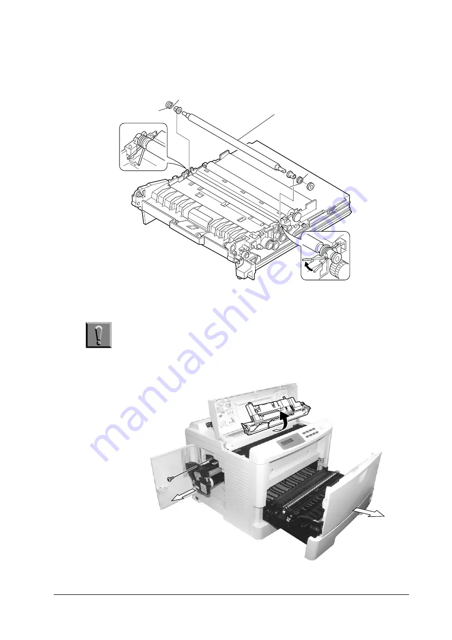
Remove the coil springs that are used to secure and press the top (metal) registra-
tion roller towards the bottom (rubber) registration roller underneath.

Removing the drum unit

Caution

Before removing the drum unit, be sure to remove the developer unit 

and draw out the paper feed unit half way. Do not attempt to forcibly 

pull out the drum without first having done all of these procedures.

Top regist.

roller

Top regist. roller

1—Remove

this screw and
pull out the

drum unit.

2—Draw the feed

unit half way out.

3—Remove the

developer unit.


Summary of Contents for FS-6750

Page 1: ...SERVICE MANUAL...

Page 2: ...duct of Xerox Corporation IBM Proprinter X 24E is a product of International Business Machine Corporation Epson LQ 850 is a product of Seiko Epson Corporation HP LaserJet 5Si and HP 7475A are product...

Page 3: ...ed chapters or sections or documentations Bold letters are also used for emphasis wherever italics may cause a confuse This symbol followed by Warning denotes that the following paragraph s includes p...

Page 4: ...Maintenance Instructs maintenance to be conducted periodically on the printer Four Operation overview Explains basic functions of the printer mechanism including engine and logic controller systems Fi...

Page 5: ...Conventions Preface v REVISION HISTORY Version Date Replaced pages Remarks 1 00 7 Nov 01 VISIT US AT OUR INTERNET HOME PAGE http www kyocera com...

Page 6: ...Conventions Preface vi This page left intentionally blank...

Page 7: ...rive page 1 6 1 3 Front and internal views page 1 7 Internal Component page 1 8 1 4 Safety information page 1 10 Laser caution label on the scanner unit page 1 10 Ozone concentration page 1 10 1 5 Ins...

Page 8: ...Printer identification labeling The printer bears its model and serial numbers on a label at its back The label also contains other safety precautions Figures below show the printer labels in two dif...

Page 9: ...n cassette Approx 250 sheets 80g or 0 1mm thickness paper MP tray Approx 100 sheets 80g or 0 1mm thickness paper Paper output tray capacity Face down tray Approx 350 sheets Face up tray Approx 250 she...

Page 10: ...urers and specifications may change without notice No responsibility is assumed by Kyocera Mita with respect to loss or damage caused by the use of these DIMMs Temperature humidity 10 to 32 5 C 20 to...

Page 11: ...is assumed by kyocera Mita with respect to loss or damage caused by the use of these memory card Table 1 3 Recommended Memory cards 1 2 Manufacturer Capacity Model SanDisk 8 MB SDCFBS 8 101 16 MB SDCF...

Page 12: ...MB TS16MFLASHCP 32 MB TS32MFLASHCP SST 8 MB SST48CF008 16 MB SST48CF016 24 MB SST48CF024 32 MB SST48CF032 48 MB SST48CF048 64 MB SST48CF064 96 MB SST48CF096 LEXAR Media 16 MB 32 MB 48 MB 64 MB 80 MB T...

Page 13: ...nd internal views 1 7 FS 6750 1 3 Front and internal views Front operator panel Feed unit release lever Paper cassette Paper ejection roller Power switch Toner bottle drum access door MP tray Feed uni...

Page 14: ...and internal views 1 8 FS 6750 Internal Component Laser scanner unit Paper ejection roller Upper unit ventilation fan Liaison board Main motor Memory card slot Regist roller clutch Feed roller clutch...

Page 15: ...T I O N Front and internal views 1 9 FS 6750 Rear cover Serial interface AC power receptacle Power switch Drum unit Main charger High voltage board unit YC13 Parallel interface YC02 Face up paper ejec...

Page 16: ...g the laser scanner unit Figure 1 2 Laser caution label Warning Use of controls or adjustments or performance of procedures other than those specified herein may result in hazardous radiation expo sur...

Page 17: ...printer on an unstable cart stand or table Near an AC wall outlet preferably one that can be used for the printer alone See Table 1 1 on page 3 The outlet should have a ground slot or an adaptor shou...

Page 18: ...ing to the printer s rated power volt age See Table 1 1 on page 3 Do not use other power sources Disconnect the printer from the power source before attempting removal or re placement of an electrical...

Page 19: ...t qual ity when used with the Kyocera s proprietary toner Kyocera do not recommend to use any refilled toner containers that may be available commercially This is because Kyocera have no means for con...

Page 20: ...atisfy the following environmental conditions Note If the toner container is removed from the printer s developer unit put it in a protective bag and keep it in a dark place Caution If the printer is...

Page 21: ...ge 2 8 Installing the DIMM page 2 9 Testing the expansion memory page 2 10 Installing the option hard disk Microdrive page 2 11 Installing the option memory card CompactFlash page 2 12 Installing the...

Page 22: ...llowing diagrams show how to unpack the printer in the shipping carton While unpacking the printer check that the parts shown below are all present Toner kit TK 26 Power cable Manuals Fillers Develope...

Page 23: ...2 2 Installing toner Take the toner container from the toner kit TK 26 for Taiwan CTK 45 for Korea supplied with the printer Give it a good shake 10 times or more Peel off the seal on the bottom of th...

Page 24: ...into place When inserting the container push firmly in order to seat it Be careful to keep the container straight and never attempt to pull it upward during insertion Caution To avoid trouble toner s...

Page 25: ...FS 6750 Installing the waste toner bottle The waste toner bottle is also supplied It must be installed inside the drum access door in the left side of the printer Open the drum access door and instal...

Page 26: ...r reservoir with a suffi cient amount of toner to continuously support a print job The period of time for this delay is approximately 15 minutes Since the automatic implementation of the developer ini...

Page 27: ...e below Refer to this table for obtaining a rough approximation on how much memory is required for a particular need Minimum memory requirements DIMM to be used Table 2 1 Minimum memory requirements P...

Page 28: ...ns Before touching the main circuit board touch a water pipe or other large metal object to discharge yourself of static electricity While doing the work it is rec ommended that you wear an antistatic...

Page 29: ...ectric shock Warning Before proceeding installation turn the printer s power switch off Unplug the printer s power cable and disconnect the printer from the computer or the network 1 Turn the power sw...

Page 30: ...corresponding protrusions in the slot 7 Close the clips 3 on the DIMM socket 4 to secure the DIMM 5 Testing the expansion memory To test the expansion memory turn printer power on and print a status...

Page 31: ...red documents can be printed at any later time For details of these functions refer to the printer s Users Manual Caution Take precautions that no foreign objects such as metal chips or liquid get ins...

Page 32: ...CompactFlash while power is on If the memory card is removed while the printer is on damage could result in the printer s electronics or the memory card 1 Turn the power switch off 2 Insert the memor...

Page 33: ...e or electric shock Warning Turn the printer s power switch off Unplug the printer s power cable and disconnect the printer from the computer 1 Turn the power switch off 2 Remove the two screws 1 then...

Page 34: ...rred that the user can clear Lit The printer is on line and ready to print Off The printer is off line The printers stores but does not print received data This is also indicates when printing is auto...

Page 35: ...sage display and printing stops after the printer finishes printing the current page Resets numeric values or cancels a setting procedure Stops the sound alarm that indicates the occurrence of an erro...

Page 36: ...cate paper sizes with only the MP tray feeding Table 2 5 Interface indications Message Meaning No interface is currently used Standard bidirectional parallel interface Serial interface RS 232C RS 422A...

Page 37: ...ates paper types The following abbreviations are used to indicate paper types with only the MP tray feeding Table 2 7 Paper type indications Message Paper type none Auto Rough Plain Letterhead Transpa...

Page 38: ...alled also appears The printer is ready to print The printer is receiving data generating graphics reading an memory card Compact Flash hard disk Microdrive or printing 4 The printer is waiting for a...

Page 39: ...y diagram of the menu selection system of the printer Private Stored Print VMB Data Parallel I F Nibble high Parallel I F Auto Parallel I F Normal Parallel I F High Speed Quick Copy Data Bits 8 Stop B...

Page 40: ...ABLO 630 Code set LQ US Emulation EPSON LQ 850 Font Internal Courier Dark Courier Regular Letter Gothic Regular Letter Gothic Dark I000 Size 012 00 point s Pitch 10 00 cpi List of Copies 001 Orientati...

Page 41: ...300 dpi Resolution 600 dpi Read Data List of Partitions Read Data Write Data Delete Data List of Partitions RAM Disk Size Read Data Write Data Delete Data List of Partitions Print Quality Opt ROM Har...

Page 42: ...nue Timer 000sec Sleep Mode Off Developer Drum LIFE Counters Others MP Tray Mode First MP Tray Size A4 or Letter MP Tray Type Plain Duplex Mode None Stack Select Face down tray Override A4 LT Off Feed...

Page 43: ...3 4 3 3 Cleaning the printer page 3 5 Main charger unit page 3 5 Paper Feed Unit page 3 7 3 4 Handling the developer unit page 3 9 Removing the developer unit page 3 9 Shipping the developer unit pag...

Page 44: ...ists Table 3 1 Life expectancy of modules Kit Module Life Remarks TK 26 26E Toner container 3 000 User replaceable Taiwan CTK 45 Toner container 7 000 User replaceable Korea DK 29 Drum unit 120 000 DV...

Page 45: ...ace the toner container to continue printing Notes on changing the toner container Observe the following cautions when replacing the toner container Do not attempt to disassemble the old toner Do not...

Page 46: ...te toner bottle The printer does not operate without a bottle installed For the reference the waste toner bottle can hold up to approx 100 g of waste toner The nominal amount of waste toner derived af...

Page 47: ...two parts the wire and grid See the picture below whenever the toner container is changed Cleaning of the main charger can be done without needing any tools thanks to its self cleaning system To clea...

Page 48: ...d with water Perform the following cleaning procedure before the pad dries Attach the grid cleaner to the printer with the pad uppermost as shown in the dia gram below When the grid cleaner is properl...

Page 49: ...ue to paper dust and debris clean the paper feed unit in the following manner Pull the paper feed unit release lever up and draw the paper feed unit all the way out until it stops Wipe the paper dust...

Page 50: ...Maintenance Cleaning the printer 3 8 FS 6750 Take out the cleaning brush supplied with the printer Clean the separation charger using the brush Separation charger...

Page 51: ...es described in 3 5 Initializing the developer page 3 11 Removing the developer unit Detach the developer connector Press the developer release levers frontwards Remove the developer unit by lifting i...

Page 52: ...Maintenance Handling the developer unit 3 10 FS 6750 Insert the developer into the container as shown below...

Page 53: ...ng the service menu in the printer s mode select routine as accessed by its front control panel Follow these steps to use this feature top to bottom For details on using the front control panel keys r...

Page 54: ...y from PC Format for the firmware files The file name for the firmware files is coded so that it implies the type applicable product and the version of the file Refer to the example below S81K7800 bcm...

Page 55: ...is displayed 7 At the DOS prompt enter Command 4 so that the system firmware ex S81K7800 bcmp and the engine firmware ex E81KA001 x are copied to the printer 8 Display 5 is displayed during downloadin...

Page 56: ...load to the root directory of the memory card 8 Remove the memory card from the PC or adaptor 9 Confirm that the printer s power switch is set to off 10 Insert the memory card into the printer s memor...

Page 57: ...ould be entered as upper case letters 6 Confirm Display 3 is displayed 7 At the DOS prompt enter Command 4 so that the message data file ex dm6602 spa is copied to the printer 8 Display 5 is displayed...

Page 58: ...firmware system download error Error code 40 57 Defective system DIMM board KP 893 for downloading error code 42 57 Defective system DIMM board KP 893 Replace the system DIMM board KP 893 Defective da...

Page 59: ...rpose tray feeding page 4 22 Paper jam sensing page 4 23 4 4 Basic engine functions page 4 24 Basic sequence of operation page 4 24 4 5 Engine controller system page 4 25 Flash memory page 4 25 Print...

Page 60: ...dpi resolution Newly developed organic photoconductor drum with no heating device Diode laser scanning Mono component toner Electrophotographic system The electrophotography system of the printer per...

Page 61: ...m is called photoconductor or photo conductor surface Charging the drum Figure below is a simplified diagram of the electrophotographics components Charging the drum is done by the main charger wire i...

Page 62: ...g the printer Cleaning the charging wire pre vents print quality problems such as black streaks caused by the oxide accumu lated around the charging wire Toner The toner is fed from the toner pack TK...

Page 63: ...ed the potential on the photoconductor is also lowered to 70 100 V effectively driving the charge through the OPC layer down to the aluminum base Scanner unit The 600 dpi scanner unit includes the dio...

Page 64: ...s The effective length of line A B below the laser beam draws on the drum becomes longer as the laser beam hits closer to the drum edges In the figure below distances represented by A and B are not th...

Page 65: ...very 1 600 inch distance horizontally The diameter of a dot is typically 70 to 80 m When KIR is on the intensity of the beam is switched in four degrees com pensating for the smoothed image Synchroniz...

Page 66: ...reas of the drum repel the positively charged toner as these areas maintain the positive charge The developing roller is also biased with an ac potential to apply compensation to the toner s attractio...

Page 67: ...Transfer The image developed by toner on the drum A below is transferred onto the paper using the electric charge attraction given by the toner itself and the transfer roller B below The transfer rol...

Page 68: ...OHP envelopes etc tend to require more bias potential for the satisfactory transferring process the transfer bias is user switchable to 2 8 kV limit by using the printer s operator panel Double sided...

Page 69: ...n nected to the end of the spiral roller B below After the drum is physically cleaned it then must be cleaned to an electrically neu tral state This is necessary to erase any residual positive charges...

Page 70: ...e magnet roller The duration of this signal is dependent on the current paper size B and turns off between pages C THVDR Transfer High Voltage DRive Turns on the transfer bias Note that the transfer b...

Page 71: ...The following charts show timings among those signals the engine controller issues to control printing The charts include different timings depending on the paper sizes and paper sources Figure 4 5 Ma...

Page 72: ...Operation theory Print timing charts 4 14 FS 6750 Figure 4 6 Main cassette A3 Feed speed FEDDR 187 658 mm s Drum speed 93 067 mm s...

Page 73: ...Operation theory Print timing charts 4 15 FS 6750 Figure 4 7 PF 26 feeder A5 or A4Y Feed speed FEED1 280 42 mm s Drum speed 93 067 mm s...

Page 74: ...Operation theory Print timing charts 4 16 FS 6750 Figure 4 8 PF 26 feeder A3 Feed speed FEED1 280 42 mm s Drum speed 93 067 mm s...

Page 75: ...Operation theory Print timing charts 4 17 FS 6750 Figure 4 9 Second PF 26 feeder A5 or A4Y Feed speed FEED2 280 42 mm s Drum speed 93 067 mm s...

Page 76: ...Operation theory Print timing charts 4 18 FS 6750 Figure 4 10 Second PF 26 feeder A3 Feed speed FEED2 280 42 mm s Drum speed 93 067 mm s...

Page 77: ...Operation theory Print timing charts 4 19 FS 6750 Figure 4 11 MP tray A5 or A4Y Feed speed MP 173 223 mm s Drum speed 93 067 mm s...

Page 78: ...Operation theory Print timing charts 4 20 FS 6750 Figure 4 12 MP tray A3 Feed speed MP 173 223 mm s Drum speed 93 067 mm s...

Page 79: ...It finally delivers the printed page to either the face down or face up tray The figure below shows the paper feeding path within the printer Following on the next page is another diagram showing loc...

Page 80: ...sensor EXITJ and finally delivered either to the face down tray or the face up tray as switched by the output stack selector tab Multi purpose tray feeding The printer recognizes the existence of pap...

Page 81: ...ration sensor combined with an actuator arm ex tending to the fuser board The actuator is in the way back at the fuser outlet The re flector at one end of the actuator is normally seated in between th...

Page 82: ...ogic controller system Paper feed system Power system Basic sequence of operation The following figure is a simplified block diagram of the printer engine system Details on each segment follow Figure...

Page 83: ...sity is lower when the clock frequency is high High voltage generator The main clock of HVCLK1 is program divided to generate the oscillator output This is up verted using a transformer in the high vo...

Page 84: ...en in the following system The interlock power supply of 5V is generated by downverting the 24V DC power using the 3 terminal regulator The 5V DC is used as the power supply for the scanner APC circui...

Page 85: ...4 3 g a pin assignment 1 4 Pin no Signal In Out Function Logic Remarks 1 VSS Power terminal Ground 2 SYSCLK OUT 4 MHZ clock output Engine CPU 3 TEST IN G A test terminal 4 HEATON OUT Fuser heater outp...

Page 86: ...FCLH OUT MP lift solenoid on output H On Neg Drive assembly 38 FEDDR OUT Cassette roller clutch on output H On Neg Drive assembly 39 MPFSOL OUT Paper feed solenoid for MP tray on output H On Neg Drive...

Page 87: ...d signal input 76 VDD Power terminal 77 ALE IN Address latch input 78 RESET IN Reset input L Reset period 79 DBRX IN Engine debugger serial data input 80 DBCLK IN Engine debugger serial clock input 81...

Page 88: ...tput Neg 111 VSS Power terminal Ground 112 FDPFUL IN Face down eject section paper full input H Full Fuser unit 113 EXITPAP IN Exit sensor paper detection input L Paper Fuser unit 114 OPSEL0 OUT Optio...

Page 89: ...Clutches registration feed manual feed Eraser Fans High voltage generator board Main motor and laser polygon motor Clutches motors solenoids within the option units The 24 V DC power is forcibly inte...

Page 90: ...ified diagram is shown on page 33 Figure 4 16 Table 4 4 Main controller specifications Item Specification CPU PowerPC405GF 160MHz System ROM size 4 MB 16 Mbit 2 RAM size Standard 16 MB 64 Mbit 2 for T...

Page 91: ...P1284DIR SELECTIN STROBE AUTOFD INIT P1284DIR U17 U22T U31 CFA20 CFA 11 2 YC05 CFD 15 0 CFCSN1 CFCSN2 CFOEN1 CFWEN1 CDET1A CDET1B CFRST1 CFWAIT1 U06 U07 Buffers EXTBOEN EXTDIR U08 U09S ROMA1 LA 21 2...

Page 92: ...ta in the raster memory is released Thus the video data are transfered to the laser scanner together with the horizontal synchronization signal and the video clock On reception of the video data the l...

Page 93: ...16 32 64 128 MB Access speed 80 ns Table 4 8 Option interface pin assignment 1 2 Pin No Signal Direction Description 1 A1 NC Reserved 2 B1 NC Reserved 3 A2 NC Reserved 4 B2 NC Reserved 5 A3 GND 6 B3...

Page 94: ...ut I O Read Strobe L 36 B18 IOW Out I O Write Strobe L 37 A19 RESET Out Reset L 38 B19 VOLT DETECT Power supply voltage detection 39 A20 D15 In Out System Data 15 40 B20 D14 In Out System Data 14 41 A...

Page 95: ...l for details The serial interface has the following features Engine interface The interface to the engine system is based on the serial interface The engine board is detachable from the printer at it...

Page 96: ...data to the controller SCLK Serial CLocK This signal is a clock for synchronization of status data and command data transmitted between the engine system and the controller and is output from the con...

Page 97: ...um unit page 5 8 Replacing the drum unit page 5 9 Main charger unit page 5 9 Top side cover page 5 10 Removing covers page 5 10 Removing front cover page 5 12 Removing the main motor page 5 13 Removin...

Page 98: ...is un plugged from the printer See Warning below Warning To avoid injury to human bodies make sure that AC power is removed and the power cord is unplugged from both the power line and the printer Scr...

Page 99: ...empt to operate the printer with a component removed Caution The printer uses electrostatic sensitive parts inside on boards laser scanner etc Provide an antistatic discharging device such as a wrist...

Page 100: ...eloper Do not place floppy disks near the developer Shipping the developer unit If the developer unit is shipped the developer must be shipped separately if the printer is shipped it must be fit in th...

Page 101: ...e removed from the printer without using tools First be sure to remove the paper cassette entirely out Otherwise the paper feed unit will not come out To remove the paper feed unit first remove the pa...

Page 102: ...le holders that hold the roller axle at both ends Hold and pull the gear at the right end of the roller up then remove the left end Cleaning the transfer roller To clean the transfer roller hold it by...

Page 103: ...paper feed unit out of the printer To remove the paper feed unit see page 5 5 Removing the paper feed unit Remove the registration rollers cover The cover is locked by two catches that lock it onto t...

Page 104: ...underneath Removing the drum unit Caution Before removing the drum unit be sure to remove the developer unit and draw out the paper feed unit half way Do not attempt to forcibly pull out the drum wit...

Page 105: ...the drum unit into the printer be sure to align the guides and rails on the drum unit with each other Do not force to slide the drum unit in unless they are properly aligned with each other Main char...

Page 106: ...rinter then pull it upwards to remove Removing covers The right side cover is snapped onto the chassis by catches and holes No screws are used To remove the right side cover release those catches and...

Page 107: ...access cover and then remove the waste toner bottle and one screw Release the catches and holes at the front and the rear from each other by inserting a small flat blade screw driver between the cove...

Page 108: ...wo screws at the front side Detach the catches at the left and right bottom of the cover as marked by circles below To disengage these catches proceed to the next step Remove the ground wire and the c...

Page 109: ...move the right side cover first page 5 10 Removing covers Remove the four screws Then remove the connector Removing the drive assembly Remove the right side cover first page 5 10 Removing covers Remov...

Page 110: ...ntil it cools down Detach all connectors from the fuser unit first Remove the four screws Pull out the fuser unit from the printer Removing the heater lamp Warning The heater is extremely hot immediat...

Page 111: ...er lamp be sure that the lamp terminal end is properly hitched by the fuser terminal Installing the fuser roller Remove the four screws to remove the cover When lifting the cover hold the heat roller...

Page 112: ...Disassembly Disassembly Main unit printer 5 16 FS 6750 Removing the thermistor and thermal cutout plate fuser up Heat roller Thermistor Thermal cutout...

Page 113: ...de horizontally Then insert the heat roller retainer back in place Removing the controller box Before removing the controller box several parts must be removed first Refer to the following pages and r...

Page 114: ...Disassembly Disassembly Main unit printer 5 18 FS 6750 Remove the screw below Remove the high voltage board at the left side of the printer To do this remove the three screws Disengage the connectors...

Page 115: ...mbly Disassembly Main unit printer 5 19 FS 6750 Remove the two screws at the left side of the printer Disengage the connectors Remove the two screws on the front side Hold the upper frame and lift to...

Page 116: ...printer 5 20 FS 6750 On the controller box remove the six screws on top and one screw at the rear side Remove the cover Removing the face down pulley assembly Remove the screw to remove the face down...

Page 117: ...per feeder PF 26 for the FS 6750 printer Before proceeding Disconnect power from the printer Remove the printer and the duplexer if installed Remove the paper path adapter as shown in the figure below...

Page 118: ...s on the top cover Remove the blanking cover and then dis engage the connectors Remove the drive roller by unlatching it both ends and then the top cover Removing the motor assembly To remove the moto...

Page 119: ...Disassembly Disassembly Option paper feeder 5 23 FS 6750 Disengage the connectors The following picture shows the motor assembly and the gears mounted on the motor bracket...

Page 120: ...Disassembly Disassembly Option paper feeder 5 24 FS 6750 This page left blank intentionally...

Page 121: ...er unit error page 6 14 6020 Abnormal high temperature error page 6 14 7001 Toner motor error page 6 15 7350 Toner refreshing mode error page 6 15 F0 F000 Main board error page 6 15 F010 System DIMM b...

Page 122: ...ards is on 6 2 Overall wiring diagram page 6 5 Liaison board KP 908 Table 6 1 KP 908 connectors Loc above Connector Connected to Check points 1 CN8 Fan large 2 CN3 Main motor E1 pin 3 MOTOR pin 1 24V...

Page 123: ...rs at the right side of the printer are mounted on the connect board These connectors derive engine signals For pin assignments refer to 6 2 Overall wiring diagram page 6 5 Table 6 2 CN13 Scanner CN1...

Page 124: ...layouts 6 4 FS 6750 Fuser board KP 499 YC 721 Table 6 3 YC 721 Pin No Signal 1 FCUP 2 24V 3 FDOWN 4 PAPFL 5 THERM 6 EXITJ 7 GND 8 5V 1 2 11 12 CN13 1 2 17 18 CN14 KP620 CN13 for laser scanner unit CN1...

Page 125: ...1 2 1 2 1 2 1 2 1 2 3 4 5 6 7 1 2 3 4 5 6 7 8 9 10 11 12 13 14 15 16 17 18 1 2 3 4 5 6 7 8 9 10 11 12 13 14 15 16 17 18 1 2 3 4 5 6 7 1 2 1 2 1 2 1 2 1 2 1 2 3 4 5 6 7 8 9 10 11 12 13 14 15 16 17 18...

Page 126: ...he printer will be ready for printing If Auto Continue is set to printing will be automatically resumed after a preset period of time 7 R Open the option duplexer rear cover then close tightly 5 37 Th...

Page 127: ...drawer securely 3 A failure has occurred with the option network interface card Check the option network interface card installed on the printer 3 7 Open the paper feed unit then close tightly S 6 Ope...

Page 128: ...d then on reformat the hard disk U8 The disk system is not installed Recheck the requirements for using the system and the devices U There is no available hard disk Microdrive space Delete unnecessary...

Page 129: ...e memory expansion DIMM Press the GO key to resume printing You can abandon printing by the CANCEL key If Auto Continue is set to printing will be automatically resumed after a preset period of time R...

Page 130: ...fer to printer s User s Manual If Auto Continue is set to printing will be automati cally resumed after a preset period of time Refer to printer s User s Manual V Look at the error code given in place...

Page 131: ...anical trouble concerning fixing power supply or optional equipment has occurred is a four digit number that indicates the type of the error The number of printed sheets is displaced after this 5 TU 8...

Page 132: ...gain Improper insertion of a connector between printer and option paper feeder PF 26 or between first cassette and second cas sette of option paper feeder PF 26 Remedy Defective duplexer DU 25 in inst...

Page 133: ...causes Corrective action The POLRDY signal is not input from the polygon motor within a certain time after the POLON signal has been output from the engine board in self diagnosis at power on or at st...

Page 134: ...ected more than a certain time after the heater has been turned on The status in which the heater is to be turned on continues more than a certain time Defective engine board KP 904 Replace the engine...

Page 135: ...orrective action Toner in the developer cannot be consumed even more than a certain time in refresh mode operation Defective engine board KP 904 Replace the engine board KP 904 Defective high voltage...

Page 136: ...expanded mem ory DIMM on the main board KP 903 Replace the expanded mem ory DIMM Table 6 20 F030 error Meaning Suggested causes Corrective action Errors concerning the main board except F0 F000 F010 a...

Page 137: ...nk Unsuccessful download ing due to power off or removal or insertion of memory card Compact Flash during download ing Write the correct down loaded data to the memory card CompactFlash Defective engi...

Page 138: ...stic 6 18 FS 6750 False error Feed unit cover open Figure 6 1 False error Feed unit cover open False error Feed unit cover open Connecttesterto 10of CN1 on KP 628 Is 10 FCOVER low Replace KP 904 board...

Page 139: ...6 19 FS 6750 Figure 6 2 Falser error Top cover open False error Top cover open Is 11 TCOVER of CN1 on KP 628 low Replace KP 628 board No Connect tester to 11 of CN22 on KP 904 Is 11 low Replace KP 628...

Page 140: ...ic 6 20 FS 6750 Figure 6 3 False error Side cover open False error Side cover open Is 1 SCOVER of CN1 on KP 628 low Replace KP 628 board No Connecttesterto 1of CN22 on KP 904 Is 1low Replace KP 628 Re...

Page 141: ...6750 Figure 6 4 False error Missing waste toner bottle False error Missing waste toner bottle Is 4 TNCON of CN1 on KP 628 low Replace KP 628 board No Connecttesterto 4of CN22 on KP 904 Is 4low Replac...

Page 142: ...e poten tial is not available on the board Check the laser scanner unit The scanner components within the scanner may be dis ordered Replace the laser scanner unit Defective main board KP 903 Replace...

Page 143: ...eplace paper with the one that satisfies the paper specifications Check the transfer roller installation The transfer roller must be supported by the bushes at the both ends Clean the bush to remove o...

Page 144: ...r for draft printing pur pose For normal printing turn the EcoPrint mode off by using the operator panel For details refer to the printer s User s Manual Check point Suggested remedy Check the print d...

Page 145: ...er unit and the fuser inlet Clean these areas and parts to remove toner Check the transfer roller If the transfer roller is contaminated with toner clean the transfer roller using a vacuum cleaner or...

Page 146: ...nsors are not correctly activated in a correct matrix of activation paper jam or printing defects like above may occur Figure 6 5 Cassette size sensors Table 6 24 Papser size matrix Paper size Switch...

Page 147: ...following 1 Press MENU 2 Press repeatedly until 9 is indicated 3 Press 4 Press repeatedly until is indicated 5 Press The display should show 76 6 Press ENTER The display should show 7 Press ENTER The...

Page 148: ...Troubleshooting Print quality problems 6 28 FS 6750 This page left blank intentionally...

Page 149: ...erface connection page A 2 A 2 Serial interface page A 4 Serial interface specifications page A 4 Data error information Snn page A 5 Changing the serial interface configuration page A 5 Serial port p...

Page 150: ...23 Ground GND 6 Data5 PAD4 24 Ground GND 7 Data6 PAD5 25 Ground GND 8 Data7 PAD6 26 Ground GND 9 Data8 PAD7 27 Ground GND 10 nAck ACKOUT 28 Ground GND 11 Busy BUSYOUT 29 Ground GND 12 PError PERROR 3...

Page 151: ...nter off line Note The Paper Empty and On Line signals are not used unless enabled by the FRPO command O2 parameter Auto Feed nAutoFd 14 This signal is used in the Epson version of the Centronics inte...

Page 152: ...422A are assigned to these pins that are not used for RS 232C according to the IBM pin assignment scheme Serial interface specifications The table below summarizes the specifications for the serial i...

Page 153: ...Touch the main board only by the edge Caution Be sure to remove the memory card first if inserted in the printer s memory card slot Refer to chapter 2 and remove the main board out of the printer Loc...

Page 154: ...mit data Reversed RS 422A 10 SDB Printer to host Transmit data RS 422A 18 RDB Host to printer Receive data RS 422A 20 DTR Printer to host Data terminal ready Other Not con nected Undefined Table A 6 M...

Page 155: ...gura tions A special cable must be prepared or obtained for the RS 422A configuration by referring to the diagram last below RS 232C for computers with a DB 9 connector RS 232C for computers with a DB...

Page 156: ...The serial interface supports the full baud rates of 300 600 1 200 2 400 4 800 9 600 and 19 200 38 400 57 600 and 115 2 k bps For adjusting serial interface parameters including baud rate parity etc r...

Page 157: ...Contents Appendix B S T A T U S P A G E B 1 Status page page B 2 Printing the service status page page B 2 Service information on the status page page B 2 Details of service information page B 3...

Page 158: ...a service status page using the MENU key Or have a PC running MS DOS and proceed as follows 1 Connect the printer to the PC via the parallel interface 2 Ensure that the printer is ready to print 3 At...

Page 159: ...page 9690 t P00 S00 F00 N00 D10 DM0301 DAN 0020 0020 1061 0811 0 0 0 0 0 0 0 AAAAAAA AAAAAAA AAAAAAA AAAAAAA DN SPL9200007 SN SPL9200010 Controller firmware version Service information Service informa...

Page 160: ...UUX Serial interface error 00 Normal bit 0 Framing error bit 1 Overrun bit 2 Parity error 9 5UUX Operator panel lock Shown only during locking 01 Partially locked 02 Fully locked 10 UUX NVRAM error S...

Page 161: ...I4 20 YUUU UUU Z Option unit equipment The first 2 byte bit0 MP tray bit1 to 6 Paperfeeder 4 5 and 6 are notsupported bit7 Duplexer bit8 to 15 Reserved The second 2 byte bit0 Face up output tray bit1...

Reviews: