background image

58    |    kvm-tec

kvm-tec    |    59

3. EXTENDER sETTiNgs

3. EXTENDER  sETTiNgs

3.7.4 USb SHaRe anY KeY

By pressing the button „B“ the USB Share any Key mode can be activated or deactivated.

If the USB share any key, the USB function can be taken over with any key.

If the function is deactivated, this works with the predefined hotkeys (see 3.7.2.) 

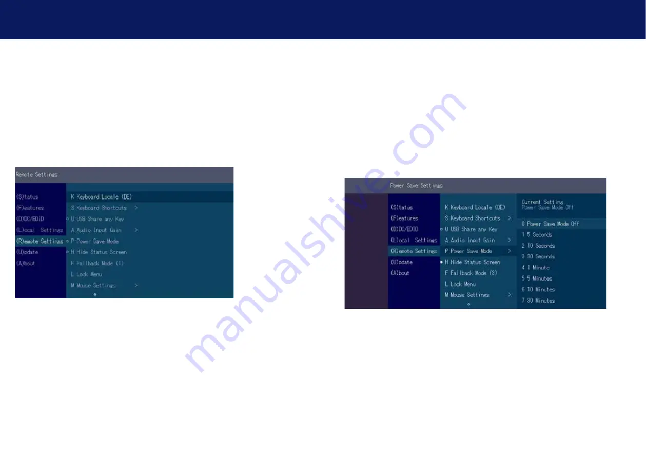
3.7.5 uSing ThE PoWER SAVing ModE

In power save mode, the Extender can switch off the video output. The power off delay can be set 
or deactivated as desired in the Power Save Setting menu.     

If the powersave mode is active, the image output at the video outputs is turned off after the time 
has elapsed. To reactivate the monitor, press any key on the keyboard or connect to a partner.

Enable and disable power save mode on the remote screen. In the main menu, press G > R.

Summary of Contents for 6012

Page 1: ...Check out our Installation Channel www kvm tec com flex master kvm tec MANUAL 6012 MASTERflex Single copper 6022 MASTERflex Dual copper 6013 Masterflex Single Fiber 6023 Masterflex Dual Fiber ...

Page 2: ...as for surveillance video walls and much more and operate control the system with centralized management Network Environemt 1 or 10 Gbit bandwith IGMP Snooping for videosharing COLLABORATE with standard network components kvm tec Extender are compatible with standard network components and all kvm tec Extender can collaborate in real time with 60Hz in full HD or 4K resolution COMMUNICATE in your S...

Page 3: ...s Menu 43 3 5 DDC Menu 45 3 5 1 DDC Main single 46 3 5 2 DDC Second dual 47 3 6 Extender Settings 48 3 6 1 Local Settings 49 3 6 2 USB Compatibility mode 50 3 6 3 USB Remote wake up 51 3 6 4 Compatibility with Linux 52 3 6 5 Bandwidth reduction 52 3 6 6 VGA Parameters 53 3 7 Remote Settings 54 3 7 1 Editing a keyboard layout 55 3 7 2 Editing keyboard shortcuts 56 3 7 3 Setting the audio volume 57 ...

Page 4: ...ace connected devices 75 4 5 Searchbox function 76 4 6 IP Management 77 5 Troubleshooting First Aid 80 6 Maintance Care 82 6 1 Extender care 82 6 2 Disposal 82 7 Warranty 83 7 1 Standard warranty 83 7 2 Extended warranty 83 8 Cable requirements 84 8 1 Requirements for CAT5e 6 7 cables 84 8 2 Requirements fiber cables 85 table of content 8 2 1 Multi Mode standard 85 8 2 2 Single Mode optional 85 9 ...

Page 5: ...ngs and instructions Keep all safety information and instructions for future reference and pass them on to subsequent users of the product The manufacturer is not liable for cases of material damage or personal injury caused by incorrect handling or non compliance with the safety instructions In such cases the warranty will be voided This product is not intended for use by persons including childr...

Page 6: ... near heaters Do not drop or hit the product Unplug all connections before cleaning the product Do not use wipes or chemicals as these could damage the surface Wipe the housing with a damp cloth Electrical electronic parts must not be cleaned Alterations to the product and technical modifications are not permitted 1 3 Technical Specifications Type KVM Extender local unit and remote unit Model MAST...

Page 7: ...9 dc connection 12V1A power supply LED STATUS yellow LINK ok green Video ok green blinking Video and USB activity 1 2 3 4 5 9 6 7 8 Remote Extender CON No Name Function 1 DVI out DVi to monitor 2 USB USB from keyboard and mause 3 audio in Audio in from microfon etc 4 audio out Audio to loudspeaker 5 kvm link connection for 12 V network cable 6 kvm link connection for CAT5 6 7 cable redundant 7 dc ...

Page 8: ...dc connection 12V1A power supply LED STATUS yellow LINK ok green Video ok green blinking Video and USB activity 1 3 6 7 4 9 2 5 8 Remote Extender CON No Name Function 1 DVI DVI to Monitor 2 2 DVI DVI to Monitor 1 3 USB USB from Keyboard and mouse 4 audio in Audio in from Microphone 5 audio out Audio to loudspeakerr 6 kvm link connection for 12 V networkcable 7 kvm link connection for CAT5 6 7 cabl...

Page 9: ...r supply redundant 9 dc connection 12V1A power supply LED STATUS yellow LINK ok green Video ok green blinking Video and USB activity 1 2 3 4 5 6 7 8 9 Remote Extender CON No Name Function 1 DVI out DVI to Monitor 2 USB USB from keyboard and mouse 3 kvm link connection for fibercable redundant 4 kvm link connection for fibercable 5 dc connection power supply 12V1A redudant 6 dc connection power sup...

Page 10: ...ion power supply redundant 9 dc conenction power supply LED STATUS yellow LINK ok green Video ok green blinking Video and USB activity 1 2 3 6 7 8 4 5 9 Remote Extender CON No Name Function 1 DVI out DVI to Monitor 2 USB USB from keyboard and mouse 3 audio in Audio in from microphone 4 audio out Audio out to loudspeaker 5 kvm link connection fiber cable 6 kvm link connection fiber cable redundant ...

Page 11: ...t 9 dc connection power supply 12V1A LED STATUS yellow LINK ok green Video ok green blinking Video and USB activity 1 2 3 6 7 8 4 5 9 Remote Extender CON No Name Function 1 dvi out DVI to Monitor 2 2 dvi out DVI to Monitor 1 3 USB USB from keyboard and mouse 4 audio in Audio in from microphone 5 audio out Audio out to loudspeaker 6 kvm link connection for fibercable 7 kvm link connection fibercabl...

Page 12: ... the meaning of each colour Also see chapter Troubleshooting Normal Operation MX only Rem Only Meaning of LED indicators Colour Blinking Physical Link Active Connection Video Extended USB Initialisation USB Data Received Identify Command Autoupdate Mode Red Yes No No Update Failed Red Slow No No No Orange Yes Yes No Orange Fast Update in Progress Green Yes Yes Yes Update Succedded Green V fast Yes...

Page 13: ...m 5 9ft opt delivery content Remote CON 1 x MV2 remote CON 1 x wall power supply 12V 1A EU plug or int plug 4 x rubber feet Make sure that the packaging contains the following content MASTERflex single fiber Delivery content Local CPU 1 x MV1 F local CPU 1 x wall power supply 12V 1A EU plug or Int plug 1 x DVI DVI cable 1 8m 5 9ft 1 x USB cable 1 8m 5 9ft 1 x VGA DVI cable 1 8m 5 9ft opt 2 x Audio...

Page 14: ... 19 Rack Shelf an alu faceplate and a power supply Under Dest Mounting kit Part Nr 6231 UMK FLEX The Under Desk Mounting kit is for underdesk mounting of the MASTERflex extender Din Rail Mounting Part Nr 6235 DINMK FLEX The DIN rail mounting is used for space saving installation in control cabinets or on DIN rails The attachment to the MASTERflex extenders is possible in several ways Vesa Mounting...

Page 15: ...2V 1A redundant Power plug 12V 1A redundant 2 5 Quickinstallation MASTERflex dual in copper 1 Connect the CON Remote and the CPU Local Unit to the included 12V 1A power supply 2 Now connect the USB cable to a USB port on your PC and connect the other end of the USB cable to the CPU Local Unit Connect keyboard and mouse to the CON Remote Unit 3 Connect the CPU Local and the CON Remote Unit with a n...

Page 16: ... main link Audio to PC Audio from PC Audio from Microphone Audio to Speaker DVI out to Monitor Power plug 12V 1A redundant Power plug 12V 1A redundant 2 7 Quickinstallation MASTERflex dual in fiber 1 Connect the CON Remote and the CPU Local Unit to the included 12V 1A power supply 2 Now connect the USB cable to a USB port on your PC and connect the other end of the USB cable to the CPU Local Unit ...

Page 17: ...reen The monitor will displays your computer s desktop or any open applications 2 9 Replacing the SFP module The MV1 F is delivered with a multimode SFP module To replace an SFP module with a different SFP module 1 Remove the black dust protector from the SFP module 2 Pull the metal latch of the SFP module forwards until it is at a right angle 3 Replace the SFP module with the other module Put the...

Page 18: ...34 kvm tec kvm tec 35 2 INSTALLATION of the extender 2 INSTALLATION of the extender 2 12 Best practice for Windows 10 Disable USB Energy Savings in Windows 10 ...

Page 19: ...n t have a Scroll Lock key open the on screen keyboard Select Start Settings Ease of Access Keyboard 4 The main menu appears with an overview of the sub menus 5 To open a sub menu press the applicable key Main menu short cuts S Status Overview Menu Status current Status U Update Flash FW Firmware update F Features Overview Overview all Features D DDC Option DDC Option Fixe Setting 1020 x 1080 L Lo...

Page 20: ...to be transmitted Video and USB show if data is currently being transmitted 3 3 Viewing the current firmware version Under A About the currently installed firmware version of the remote CON and local CPU Extender is displayed e g 4267 You will find the screenshot in menu item 3 10 3 4 Features Menu By pressing the F button the Fatures menu is displayed Features Menu P Point to Point Mode Enabled D...

Page 21: ... By pressing the key S you can switch the USB save feature on and off 3 4 4 Display the last received image Freeze Last Image With the freeze last image function the last image received can be displayed instead of a black screen when the remote extender CON is disconnected from the local extender CPU To show that it is the last image received the frame of the image will blink red To enable or disa...

Page 22: ...he other port immediately takes over In such a case you will receive an alarm and can see which port has failed Power Redundance Alert Only for devices with two DC sockets SEC POWER LOST PRIM POWER LOST Link Redundance Alert Only for single devices with two RJ45 jacks PRIM LINK LOST SEC LINK LOST BOTH LINK LOST Oder SEC LINK ERROR with active redundancy PRIM LINK ERROR with active redundancy 3 4 7...

Page 23: ...he test the status displays the sum of all errors that occurred 3 5 DDC Menu The DDC Information menu allows the user to specify which DDC information is used by the PC Definition of the DDC information used by the PC 1 make sure that the main menu is open Press the O button and the DDC option menu will be displayed Press 0 to display the DDC information of the monitor connected to the remote CON ...

Page 24: ...46 kvm tec kvm tec 47 3 EXTENDER settings 3 EXTENDER settings 3 5 1 DDC Main single 3 5 2 DDC Second dual ...

Page 25: ...esponding button Display the Extender Settings menu 1 Make sure that the main menu is open 2 Press the L button The Local Settings menu is displayed 3 Press the R button The Remote Settings menu is displayed 3 6 1 Local Settings View the local or remote Extender settings Press the L button to display the Local Setting menu C USB Compatibility Mode Disabled Enabled W USB Remote Wakeup Disabled Enab...

Page 26: ...s to abort the boot process This can be avoided with the USB Compatibility Mode The USB compatibility mode can be enabled or disable To enable disable the USB compatibility mode 1 From the Extender Settings menu press the L key The LOCAL SETTINGS menu appears 2 Press the U key to enable or disable the USB compatibility mode 3 6 3 USB Remote wake up The PC can be set into sleep mode and can be reac...

Page 27: ...F1 moves the display range upwards Pressing F4 moves the display range down Pressing F2 moves the display range to the left Pressing F3 moves the display area to the right Pressing F5 reduces the image zoom out Pressing F6 enlarges the image zoom in Pressing the space bar changes the speed of the above mentioned settings The speed can be switched between 1 and 10 Pressing M switches the video mode...

Page 28: ...oard Local menu lets you switch between keyboard layouts for navigating the on screen display menu OSD You can choose between French FR English EN and German DE Selecting a keyboard layout 1 Press R in the Extender Settings menu The Remote Settings menu appears 2 Press the K key The Keyboard Locale menu opens Press E to select English EN Press D to select German DE Press F to select French FR ...

Page 29: ...rrows to select a command 4 Press E to edit the shortcut To edit Press a single key Edit the frequency with left and right arrows OR Press a key combination dual single 3 7 3 Setting the audio volume The volume of the audio input microphone on the remote unit can be changed The default value is 5 but can be set to any value in between 0 and 9 At 0 the audio input on the remote unit is disabled Set...

Page 30: ...the predefined hotkeys see 3 7 2 3 7 5 Using the power saving mode In power save mode the Extender can switch off the video output The power off delay can be set or deactivated as desired in the Power Save Setting menu If the powersave mode is active the image output at the video outputs is turned off after the time has elapsed To reactivate the monitor press any key on the keyboard or connect to ...

Page 31: ...ove the status screen and the image remains black kvm tec 61 3 Extender Settings 3 7 7 Change keyboard fallback modus To use the OSD menu the keyboard on the remote device must be identified For most keyboards use the 0 setting When using USB some mice act like a keyboard In this case select fallback mode 1 or 2 ...

Page 32: ... mode Mouse glide Switch and Multiview Commander With this function the horizontal and vertical speed can be adjusted 3 7 10 Monitor sync strength The frame start of the monitor is synchronized with the graphic card Some monitors are very sensible regarding frequency changes Therefore the changes should be done slow and the synchronization takes a bit more time The monitor sync strength can be adj...

Page 33: ...two step process In the first step the firmware is loaded into the device and in the second step the update is performed All extenders in the system file can also be updated together For the update activate the Settings window and select the folder from which the firmware file is to be uploaded The list of bitmaps is displayed under MX Firmware Then transfer the firmware and the update will be don...

Page 34: ... 32 3 Extender Settings 3 9 Unlock an upgrade 1 Make sure the main menu is open 2 Press the M key The Options Overview menu opens The device ID will be shown 3 Order the unlock code from your supplier by providing them with the 9 character device ID and the serial number of your KVM extender 4 Press M key to enter the unlock code 5 Enter the unlock code your supplier provided 6 The extender will a...

Page 35: ...2 Press the M key The Options Overview menu opens The current USB Memory status is displayed Enabled or Disabled 3 Press 1 to enable or 0 to disable the USB Memory upgrade 3 9 2 Enable or Disable Sound upgrade This upgrade enables analog sound transmission in both directions in CD quality For a description of how to enable or disable the sound upgrade see in Chapter 3 9 Unlock an upgrade 3 9 3 Ena...

Page 36: ...tivated upgrades You can also see the current firmware version here single dual 3 Extender Settings 4 network settings and Management Switching Sys tems All network settings user administration and extender management are done via the included Switching Manager software and all functions are described in the Switching Manager 2000 manual You can download the manual from our website www kvm tec com...

Page 37: ...ailable devices that the user can connect to are displayed here 4 Network Settings 4 2 PUSH GET List Display of all extenders that can be shared The current image of the workstation can be shared with other remote units via this list 4 Network Settings ...

Page 38: ...lace connected devices Logging in to the local PC in the main menu press A Enter your username and password Disconnecting from an encoder in the main menu press D Enabling a direct connection If you are not connected through a network switch you can connect directly to an encoder with point to point mode In the main menu press P After logging in the user receives his personalized lists Devices Fav...

Page 39: ...rch for the Extender you want to see Press the Return key you should now see a reduced list of Extenders 4 Network Settings 4 Network Settings 4 6 IP Management The KVM extenders from kvm tec support three different addressing methods The IP Manage ment menu is only accessible in the active Matrix Switching Mode under Features Default In default mode each Extender generates an IP address using the...

Page 40: ...the assignment of network addresses by a DHCP server Static IP In Static IP mode the IP addresses can be assigned via the OSD It is necessary to be connected to a local partner to be able to transmit IP addresses The blue values show the currently assigned IP addresses With the arrow keys up down you can overwrite the respective IP address The addresses can be overwritten by entering a valid 12 di...

Page 41: ...lish audio connection plug stereo jack to the audio output of the PC green connection with local IN remote headset OUT Establish microphone connection plug stereo jack to the microphone input of the PC pink connection with local OUT Connect the microphone to the Remote IN First Aid kvm tec smart connection We are here for you to answer your questions about installation Manual download www kvm tec ...

Page 42: ...ould otherwise be caused by improper treatment of waste equipment The recycling of materials contributes to the conservation of natural resources Therefore do not dispose of your old electrical and electronic equipment with the unsorted municipal waste The packaging is made of environmentally friendly materials which may be disposed through your local recycling facilities By disposing of the packa...

Page 43: ...he length The shield should be contiguous and connected to both ends A shielded patch cable is allowed for connection to the device Schema EIA TIA 568 B 8 2 Requirements fiber cables 8 2 1 Multi Mode standard A Multi Mode fiber cable should meet the following requirements Maximum length should be 500 m The MV1 F includes a fiber Multimode SFP Module which allows a transmission distance of up to 50...

Page 44: ...Switching System Datasheet recommended Switche 9 1 Recommended Switches 10 Address phone emails If you have any questions about our products please contact kvm tec or your dealer kvm tec electronic gmbh Gewerbepark Mitterfeld 1A 2523 Tattendorf Austria Phone 0043 0 2253 81 912 Fax 0043 0 2253 81 912 99 Email support kvm tec com Web www kvm tec com Find our newest updates and FAQs on our homepage h...

Page 45: ...88 kvm tec 11 Notes ...

Reviews: