


23
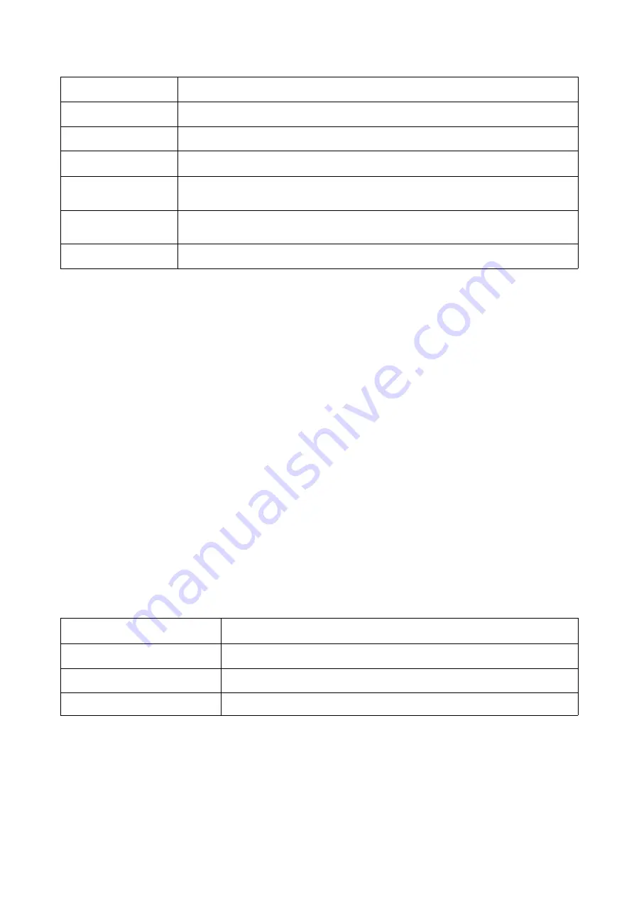
main screen with this function. The choices and their meanings are given in the table below:
Choice
Meaning
ALL
Lists all of the ports on the installation.
QVIEW
Lists only the ports that have been selected as Quick View Ports.
POWERED ON
Lists only the ports that have their attached computers powered on.
POWERED ON +
QVIEW
Lists only the ports that have their attached computers powered on and
have been selected as Quick View Ports.
QVIEW + NAME
Lists only the ports that have been selected as Quick View Ports and have
name.
NAME
Lists only the ports that have names.
Move the highlight bar to the choice you want, then press [enter]. An icon appears before the choice
to indicate that it is the currently selected one.
After you make your choice and press [Enter], you return to the OSD main screen with the newly
formulated list displayed.
F4 QV
QV function can select port as Quick View. Move the highlight bar to a port, press [F4], an icon of
up triangle appears. Press [F4] again, the icon disappears.
F5 EDIT
EDIT function creates or edits the name of a port. Press [F5], a pink edit box will appear on the
screen. Input name, and then press [Enter], the port is set a name and it will also appear on the
screen.
F6 SET
SET function configures the OSD menu. Move the highlight bar to an option, press [Enter] to enter
a setting option.
CHANNEL DISPLAY MODE: Mode of small tip window
。
Choices and meanings are below:
Choice
Meaning
PN + NAME
Tip window displays port number and port name.
PN
Tip window displays port number.
NAME
Tip window displays port name.
Move the highlight bar to an option and press [Enter] to select it.
CHANNEL DISPLAY DURATION: Time the tip window last.
Options are following:
3 SECOND The tip window lasts for 3seconds.
ALWAYS ON The tip window always on the screen.
Summary of Contents for AS-7100 Series
Page 8: ...8 DIMENSION ...
Page 13: ...13 Structure Usage ...
Page 14: ...14 ...
Page 15: ...15 Assembling Disassembling The device can be assembled and disassembled as following ...
Page 16: ...16 ...
Page 18: ...18 4 Use the screws supplied with this package to attach the bars to the rear of the switch ...


