2-10
TracVision 6 Installation and Technical Manual
2.3.5 Installing the Switchplate
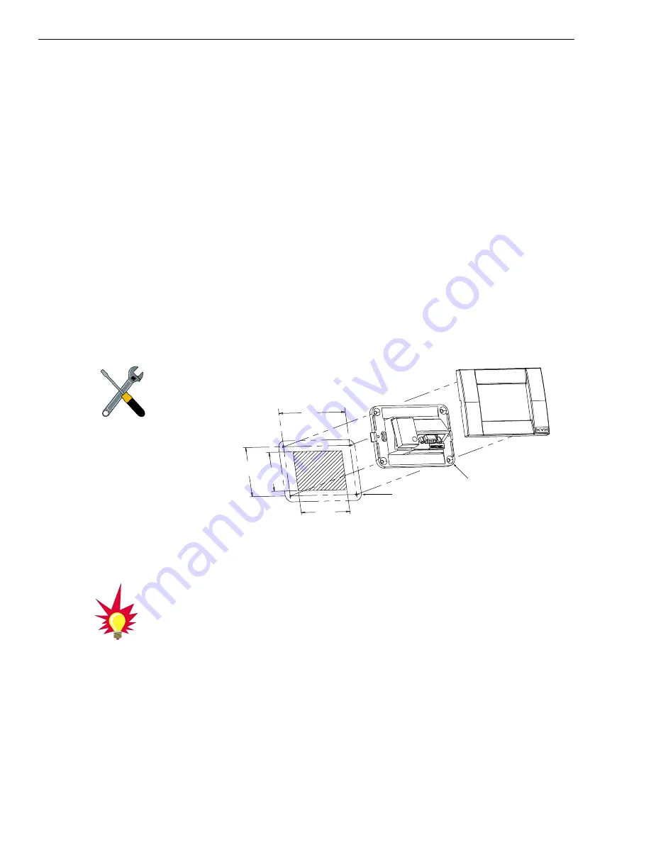
After completing the switchplate wiring process, you must install
the switchplate itself. This process, detailed in the following
steps, is illustrated in Figure 2-12.
1. Drill four
5
⁄
32
" (4 mm) holes in the support frame.
2. Fit the switchplate assembly and support frame
into the panel cutout made in Step 2 in
Section 2.3
and flush to the mounting surface.
2. Drill four
3
⁄
32
" (2.5 mm) holes in the mounting
surface using the countersunk holes in the support
frame as the template. Secure the support frame
and switchplate assembly to the mounting surface
using the four #6 self-cutting screws.
3. Snap the front cover into place to cover the screws
and support frame.
2.3.6 Connecting an Antenna RF Signal Cable
to the IRD
The RF signal cable is fitted with F-type connectors. One end
should be connected to the plug labeled “RF1” on the base of the
TracVision 6 system. The other connector should be connected to
the IRD plug labeled “LNB” or “ANT/SAT.” If a second IRD is to
be hooked up to the TracVision 6 antenna unit, the RF cable for
the second IRD should be connected to the plug labeled “RF2”
while the other end is connected to the IRD plug labeled “LNB”
or “ANT/SAT” on the second IRD.
3.82"
(97 mm)
2.36"
(60 mm) 2.05"
(52 mm)
3.19"
(81 mm)
A. Panel Cutout
B. Support Frame
C. Front Cover
5
/
32
" (4 mm)
3
/
32
" (2.5 mm)
Figure 2-12
Mounting the Switchplate
Support Frame and Front Cover
Before securing the switchplate to
the mounting surface, be sure to
strain relieve the wires connecting
to the switchplate connectors.
Several tie-wraps have been
provided to aid in strain relieving
the wires.
The IRD that is connected to the
RF1 cable controls which satellite
the antenna is tracking. The IRD
connected to RF2 can select
different channels on that satellite
but not change the satellite
selection itself.


