background image

Presentation of the machine

19

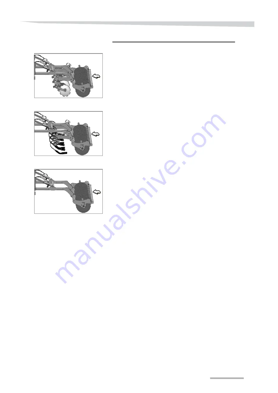
There are three configurations mounted on roller arms:

Levelling discs + roller [+]

Working depth check by roller.

The levelling is performed by notched discs mounted on rubber 
spring safety.

Compaction is performed by the rear roller.

Tines + roller [+]

Working depth check by roller.

The levelling is performed by tines on spring mounted safety 
mechanisms.

Compaction is performed by the rear roller.

Roller only [+]

Working depth check and compaction by roller.

Summary of Contents for Enduro

Page 1: ...Enduro Enduro Pro User manual Translation of the original document Issue 05 2019 Date of printing 05 2019 Language EN From serial No RFCSHxx Reference No A135723940 ...

Page 2: ...ndes Génusson is the holder of all copyrights and rights of use No copy translation or use including in other media of this user manual or part of this user manual is allowed without the express authorisation of Kverneland All rights reserved The contents of this user manual are subject to change without notice Technical data subject to modification Kverneland Group Les Landes Génusson S A S 9 rue...

Page 3: ...sportation width 33 Lighting and signalling 34 Adjustments 35 Flexibility 35 Adjustment of working depth 36 Adjusting the edging disc levellers 37 Adjustment of rear accessories 38 Rollers 43 Actiflex roller 45 Unhitching 46 Frame unfolded 46 Frame folded 46 Safety instructions 47 Maintenance 48 Cleaning 48 Maintenance 48 Storage 48 Maintenance 49 For your safety 49 General 51 Greasing 52 Location...

Page 4: ...structions relating to the use and maintenance of the machine Meaning of symbols A variety of symbols is used to provide clarity Their meaning is as follows A dot is followed by a list A triangle precedes operations to be carried out An arrow refers back to other passages in the text Also pictograms clearly indicate important instructions NOTE The term Note indicates advice and comments on use A k...

Page 5: ...ers are applied to the machine Do not remove these stickers If they are illegible or no longer properly stuck order new ones and fit them in the corresponding positions Meaning of symbols Read and follow the user manual and the safety instructions before switching on the machine or doing work on it Carrying passengers on the moving machine is prohibited during transport and when working There is a...

Page 6: ...machine Presence of cutting and contusive edges Before you start to make any adjustments make sure that all the parts of the machine are immobile Make sure that you do not bump against the machine The tractor s hydraulic pressure must not exceed 210 bars 3045 PSI Check the hydrayulic pressure Applies to machines fitted with an open return line Indicates a hydraulic connection that cannot accept pr...

Page 7: ... the machine The coulters are made from treated steel To avoid contact between two hard parts use the specific Knock on tool During assembly or disassembly operations never directly hit the coulters with a hammer This risks causing shards breaking parts and causing serious injury For safety reasons the following safety equipment is mandatory A visor or protective goggles to guarantee maximum prote...

Page 8: ...the cause of the incident Make repairs before continuing No repair operations should be carried out on the machine unless all measures have been taken to prevent unintentional start up uncouple the power take off and or hydraulic hoses tractor engine switched off for example chocks have been placed under the chassis to prevent it falling the vehicle has been immobilised using the appropriate syste...

Page 9: ... controls such that the hitch does not move during handling the hitch must be locked and should not come detached by itself in the lower position The weight distribution is altered when the machine is hitched The maximum load per vehicle axle see manufacturer s information should not be exceeded If there is insufficient loading on the front axle extra weights must be installed so that control over...

Page 10: ...prevent accidental unfolding For machines with a transport axle secure the locking system in place prior to travelling on the road During travel the lift control must be positioned so as to prevent the tool from being accidentally lowered Check that your hitch meets local road safety requirements Where applicable it is your responsibility to install and test transport equipment for example lightin...

Page 11: ...oving machine forward movement movement of any part of the machine movement of the tractor lift For equipment with lateral deflectors or any other accessory with vertical adjustment it is recommended that you maintain a safe distance in case the equipment accidentally falls during adjustment Wearing safety shoes is recommended Serious injury even death can result from contact with power lines Take...

Page 12: ...bly disassembly and adjustment It is strictly forbidden to disassemble springs used as safety devices for working parts This operation must only be performed by specialists Regularly check that bolts are tight tyre pressures are correct and the hydraulic circuit is in good condition Before doing any welding disconnect the electrical boxes where present and disconnect the tractor s alternator and b...

Page 13: ...rs to from the tractor s hydraulic system when the tractor machine assembly is no longer pressurised Hydraulic system The hydraulic system is pressurised When connecting the hydraulic system make sure that the tractor system and tool are not pressurised Connect the hydraulic system following the instructions in the manual Colour code sockets so as to prevent incorrect connections inverting functio...

Page 14: ...ler decline any responsibility for damage caused by use other than normal use The user assumes all risks Compliance with the conditions of use includes compliance with the manufacturer s user instructions The safety instructions detailed above and rules regarding general safety occupational health and road traffic must also be followed Modifications to the tool made by the customer or the use of s...

Page 15: ...Presentation of the machine 15 General Description D B A C Reference Designation A Hitching B Roller s C Levelling accessory D Stubble cultivator module ...

Page 16: ... 5 cm 30 cm 5 cm 35 cm 5 cm 30 cm 5 cm 35 cm Depth control Hydraulic with spacers Hydraulic con tinuous Hydraulic with spacers Hydraulic con tinuous Levelling option Tines or levelling discs Levelling adjustment Mechanical Mechanical or hydraulic Mechanical Mechanical or hydraulic Rollers Cage roller Double cage Actiring Actiflex Actipack Actipress Twin Total weight with cage roller 1 750 kg 3 858...

Page 17: ...y tine type Image Thread Size Bolted coulters Plough point 60 mm 2 3 8 Plough point 60 mm 2 3 8 Fin 320 mm 12 1 2 Knock on coulters 80 mm 3 80 mm 3 Fin 320 mm 12 1 2 150 mm 6 250 mm 10 320 mm 12 1 2 Carbide coulters 70 mm 2 3 4 70 mm 2 3 4 Fin 320 mm 12 1 2 ...

Page 18: ...otched discs mounted on rubber spring safety Compaction is performed by the rear roller Tines roller Working depth check by roller The levelling is performed by tines on spring mounted safety mechanisms Compaction is performed by the rear roller Roller only Working depth check and compaction by roller Image Dimension Enduro and Enduro Pro Tine protector 60 mm 2 3 8 Deflector 80 mm 3 Spiral deflect...

Page 19: ...er The levelling is performed by notched discs mounted on rubber spring safety Compaction is performed by the rear roller Tines roller Working depth check by roller The levelling is performed by tines on spring mounted safety mechanisms Compaction is performed by the rear roller Roller only Working depth check and compaction by roller ...

Page 20: ...mm 21 1 4 Compaction and crumbing of all types of soil but limited in excessively stony conditions Actiflex roller diameter 580 mm 23 5 8 Compaction and crumbing of all types of soil Double tube roller bar Crumbing levelling and depth control for all types of soil Actipress Twin crossing roller diameter 565 mm 22 1 4 Crumbing levelling consolidation and improved depth control for all types of soil...

Page 21: ... warning panels on the tractor must be perfectly visible If this is not possible you must install lights and a licence plate on the machine If necessary contact your dealer to order a new lighting kit Hydraulic discs and side tines Used to withdraw and extract the edge levelling components from the cab Available only on rigid machines ...

Page 22: ... protectors with deflectors In this case ensure you follow the configuration diagrams opposite that show the ex factory configuration in order to get a better result when working Tine deflectors Tine protectors Spiral Left Spiral Right Centred x1 x1 0 x8 Enduro Enduro Pro 3 00m 9 10 285mm 11 pitch ...

Page 23: ...Presentation of the machine 23 Tine deflectors Tine protectors Spiral Left Spiral Right Centred x1 x1 0 x8 Enduro Enduro Pro 3 50m 11 5 285mm 11 pitch ...

Page 24: ...Presentation of the machine 24 Optional configu rations Deflectors Tine deflectors Tine protectors Spiral Left Spiral Right Centred x1 x1 x8 0 Enduro Enduro Pro 3 00m 9 10 285mm 11 pitch ...

Page 25: ...Presentation of the machine 25 Tine deflectors Tine protectors Spiral Left Spiral Right Centred x1 x1 x8 0 Enduro Enduro Pro 3 50m 11 5 285mm 11 pitch ...

Page 26: ...Presentation of the machine 26 Spiral deflectors Tine deflectors Tine protectors Spiral Left Spiral Right Centred x5 x5 0 0 Enduro Enduro Pro 3 00m 9 10 285mm 11 pitch ...

Page 27: ...Presentation of the machine 27 Tine deflectors Tine protectors Spiral Left Spiral Right Centred x6 x6 0 0 Enduro Enduro Pro 3 50m 11 5 285mm 11 pitch ...

Page 28: ...e levelling system to the rear of the machine Check the alignment of the roller with the chassis Tighten the attachments Check that all attachments are tight Rear accessory configurations Levelling discs Enduro Pro The machine may be delivered partly disassembled In this case carefully follow the assembly instructions contained in the assembly handbook Enduro Pro 3 00m 9 10 ...

Page 29: ...9 Enduro Edging discs with the hydraulic option When the edging discs with hydraulic option is installed the central discs are no longer offset but at the same level Enduro Pro 3 50m 11 5 Enduro 3 00m 9 10 Enduro 3 50m 11 5 ...

Page 30: ...Receipt and assembly 30 Levelling tines Enduro Pro Enduro Enduro Pro 3 00m 9 10 Enduro Pro 3 50m 11 5 Enduro 3 00m 9 10 ...

Page 31: ...Receipt and assembly 31 Enduro 3 50m 11 5 ...

Page 32: ...ption Available only on rigid machines After transport on road reconnect the hydraulic hoses used for outer levelling to the tractor Adjust the machine as required Extract the edge levelling Caution Comply fully with safety instructions Never stand between the tractor and the machine during the coupling operation Risk of collision All folding and unfolding operations must be made with the struts r...

Page 33: ...hat the machine complies with current requirements Make sure that the machine is equipped with suitable signalling devices Make sure that the machine is equipped with suitable warning and safety devices Make sure that the machine complies with the following points permitted transport width permitted weight permitted axle loads permitted tyre load limits permitted total weight Make sure that the ma...

Page 34: ...ice Actuate the distributor to fully retract the tubes of the edge levelling device Disconnect the edge levelling function hydraulic lines from the tractor to avoid any accidental operation during transport Lighting and signalling Ensure that the lighting reflectors licence plate sign boards and warnings are always fully visible If this is not possible fit lights and a number plate to the machine ...

Page 35: ... mixing required power and levelling If the machine tines are equipped with right and left deflectors then when starting up it is necessary to check the levelling quality If required it is possible to invert one or several pairs of deflectors in order to improve mixing or levelling quality Width mm 60 320 80 320 150 250 320 70 320 Width inches 2 3 8 12 1 2 3 12 1 2 6 10 12 1 2 2 3 4 12 1 2 Depth c...

Page 36: ...g mechanisms have additional adjustments Enduro Pro On machines fitted with a parallelogram system the working depth is adjusted from the tractor cab The arm position determines the working depth The label affixed to the mounting indicates a theoretical depth It must be controlled and readjusted if necessary Machine horizontal alignment must also be checked and readjusted CAUTION Danger of crushin...

Page 37: ...ributor to set the cylinders against their spacers Place the machine on the ground and move forward a few metres If necessary correct the length of the third point so that the chassis remains parallel to the ground Adjusting the edging disc levellers An uneven ground surface may require adjusting the height of the edging disc levellers The height can be adjusted by 2cm by moving the two bolts A in...

Page 38: ...lar position of the levelling elements is optimum but a slight angular adjustment can be carried out using the different positions of the parts C Adjusting the height Raise the machine Raise le levelling as much as possible using the handles A Place the machine on the ground keeping it horizontal Using the handles A lower the levelling down to the ground without penetrating Using the rule B check ...

Page 39: ...e pins C from the axes Fit the wrench on the nut B Raise the wrench B to decrease the levelling Remove the axes C Insert these axes into the desired adjustment holes Refit the pins into the axes C If the working conditions change return to position A Enduro The levelling is positioned on arms linked to the roller mountings by handles The height of the levelling tines follows the height of the roll...

Page 40: ...ck that the adjustment is the same on both sides Correct the levelling angle to achieve the same disc working depth Remove the pins from the axes D Fit the wrench on the nut C Raise the wrench to decrease the levelling Remove the axes D Insert the axes into the desired adjustment holes Refit the pins into their axes D Test and then correct the setting depending on the quality of levelling obtained...

Page 41: ... the element until socket B touches plate D Put back pin C in the free hole closest to plate D Mechanical 3 50 metres Remove pins A C F and G blocking the position of sockets B and E Place sockets B and E in the required position Lock sockets B and E using pins A and F Extract the element until sockets B and E touch plate D Put back pins C and G in the free holes closest to the plates D and H ...

Page 42: ... the cylinder distributor to extract the tine until socket B touches plate D Hydraulic 3 50 metres Remove pins A and F blocking the position of sockets B and E Place sockets B and E in the required positions Lock sockets B and E using pins A and F Actuate the cylinder distributor to extract the levelling elements until sockets B and E touch plates D and H ...

Page 43: ...epth We recommend exerting the lowest possible pressure on the knife skids as excessive pressure could cause Increased wear of the knife skids increased traction power requirement a risk of blockage etc The scrapers C do not have to be adjusted when changing from one setting to another The scrapers are only used in the OFF position to clean the central tube Adjustment procedure Set the knife skids...

Page 44: ...h C on the welded nut located on the lower part so that the rear rail is supported While holding the wrench C in position loosen the countersunk screw A with the small wrench B so that it protrudes by about 1 cm from its conical housing Swing the rail to the required position 1 2 3 or OFF Still holding the wrench B in position fully tighten the countersunk head screw A Tighten the locknut Go to th...

Page 45: ...ou are working in the autumn and you want to sow in the spring You are not planning to sow for a long time Dismantle the levelling blade rail Loosen the nuts A and B on each mounting between 3 and 6 mountings depending on the width Remove the mountings Raise the levelling blade rail Put the mountings back in their position Centre the levelling blades with respect to the rings Tighten the nuts A an...

Page 46: ...refer to store the machine with the frame folded In this case Fold up the frame Ensure that the folding cylinders are fully retracted Place the machine on flat and sufficiently stable ground Lower the machine until the tines touch the ground Actuate the depth control wheels so that the central section wheels are in contact with the ground Ensure that there is no obstacle or irregularity in the soi...

Page 47: ...ions There is a serious risk of injury when unhitching the machine To prevent any danger Immobilise the tractor Make sure that the machine is on flat and sufficiently stable ground Never stand between the tractor and the machine Actuate the hydraulic lift slowly and carefully ...

Page 48: ...ur machine in good condition during storage Clean it Lubricate the various points listed in the Maintenance section Store your machine on a flat stable surface Apply grease on the jack rods to prevent corrosion Fixed machines Storage Specificities Make sure that the depth control cylinders are fully extracted Position the machine on a stable and level surface Disconnect the hydraulic hoses Disconn...

Page 49: ...ngth and material quality should be used If parts other than original replacement parts are fitted the warranty is void Prevent any unintentional movement of the machine Carry out repairs or maintenance or eliminate malfunctions with the machine hitched only when the power take off has been deactivated the engine is switched off the ignition key is removed the electronic control system has been de...

Page 50: ...tect your skin Protect your skin when handling oils or lubricants by applying a protective cream on the skin or by wearing oil and lubricant proof gloves Oils may cause health problems Never use oil to clean your hands Never use oil or lubricants to clean your hands Swarf in such liquids can also cause injury Do not wear clothing contaminated with oil Remove garments heavily soiled with oil as qui...

Page 51: ...a brief explanation of the main maintenance points Work Execution Lubricate Apply grease on sliding surfaces with a brush Oil Unless otherwise indicated use only vegetable oils such as rape seed oil Mineral oils are not suitable Used oils are dangerous to your health and their use is strictly prohibited Replacement Replace the part concerned by following the instructions contained in the maintenan...

Page 52: ...machine s greasing points quickly For all greasing operations the machine must be in the park position with the tines on the ground to avoid any risk of crushing The wear rings must be changed when they stop protecting the different parts of the machine If used wear rings are not replaced damaged machine parts will not be covered by the warranty If damaged rings are not replaced their housing may ...

Page 53: ...Maintenance 53 Location of the wear rings Enduro Pro Crank X Double tube roller bar X Image Part Frequency Every day Every 40 hours Every year ...

Page 54: ...Maintenance 54 Enduro Double tube roller bar ...

Page 55: ...washer Values provided for assembly with no special lubrication Diameter of screw Quality 8 8 Quality 10 9 Quality 12 9 N m ft lbf N m ft lbf N m ft lbf 3 1 41 1 04 2 07 1 53 2 43 1 79 4 3 22 2 38 4 74 3 50 5 5 4 06 5 6 4 4 72 9 4 6 94 11 8 12 6 11 1 8 19 16 3 12 03 19 1 14 10 8 27 20 39 29 46 34 10 53 39 78 58 92 68 12 92 68 136 100 159 117 14 148 109 218 161 255 188 16 232 171 341 252 399 294 18...

Page 56: ...ce a year or more frequently if used intensively and tighten if necessary These tightening torques are shown on the label affixed to the machine Use only the screws supplied The securing screws supplied are special screws for specific requirements Commercially available screws will not stand up to the stresses on the machine If you use inappropriate screws or if you do not tighten them to the reco...

Page 57: ...lling element wear Levelling disks Replace the levelling discs A when they become too worn Replace the pads B when they become too worn Levelling tines Change the blades of the levelling tines A when they become too worn ...

Page 58: ...Once the tine has returned to the low position check that it is tight and does not jam at any point Never loosen more than one spring at the same time Carry out the adjustment on one spring Loosen the spring Move onto the next spring If you loosen several springs at the same time the machine may tip over This could result in injuries Any tine that is abnormally blocked in the raised position may s...

Page 59: ... not wear in the same way if the ground is dry or damp Damp ground The surface wears more rapidly than the part length A hole will appear through the bulb indicating that the coulter must be changed so that it can continue to protect the support Dry ground The bulb plays a protective role until the end If the coulters are not replaced in time the over worn parts could fall off during work and the ...

Page 60: ...Hit the other end with a hammer Mounting Bevelled Knock on tool Hammer 1 5 kg 3 3 lbs minimum Place the end of the coulter point in the slot in the Knock on tool Hold the Knock on tool firmly taking care not to be pinched when hitting Give two or three firm hits to the coulter with a hammer in the direction of the blocking system to guarantee that the part remains in the support Keep out of the da...

Page 61: ...e 61 Distributing plough points Standardisation of the symmetrical installation of 60 mm 2 1 2 points irrespective of the type of machine and arrangement of tines Right side straight points Left side left points ...

Page 62: ...x Check that the screws are still tight after several hours of use Regularly check the wear on the levelling blade coulters A Replace them before wear can cause the part to be lost during operation After use and before storage it is recommended that the roller is thoroughly cleaned to remove any earth attached to it which may cause a nuisance when resuming work A Levelling blade B Coulter wear zon...

Page 63: ...Hydraulic diagrams 63 Hydraulic diagrams Hydraulic unit Enduro and Enduro Pro Depth control Hydraulic levelling extensions ...

Page 64: ...nsport Any claims must be made to us in writing within six 6 days The warranty will apply only if the conditions appearing on the delivery contract have been met by the buyer The warranty cannot apply if the machine has been repaired by the customer without the dealer s approval has been modified by fitting non original parts ...

Page 65: ...sent to a scrap metal recycling centre Tyres Tyres can be sent to a tyre recycling centre Hydraulic fluid Collect hydraulic fluid in clean sealed containers designed for this purpose Avoid using food containers or drinks bottles Take hydraulic fluid and hoses to an appropriate recycling centre Do not spread on the ground or pour into sewers used grease or other substances such as motor oil hydraul...

Page 66: ...lth and safety requirements stipulated in EC Directive 2006 42 EC To implement the safety and health requirements stipulated in the EC Directive the following standards have been taken into account ISO 12100 1 2003 ISO 12100 2 2003 ISO 4254 1 2009 Kverneland Group Les Landes Génusson S A S 9 rue du Poitou 85130 LES LANDES GENUSSON FRANCE Les Landes Génusson 2 11 2013 Hasan Kesek Chairman and autho...

Page 67: ...lling 16 Lubricants 50 M Maintenance 48 Manager 5 Metal parts 65 O Oils 50 P Pads 57 Pictograms 4 S Safety Coupling 9 General recommendations 8 Hydraulic system 13 Maintenance 12 Uncoupling the machine 13 Use 11 Safety rules 8 Safety symbols 5 Storage 48 symbols 5 T Tightening torques 55 Transport 10 Tyres 65 U User safety 5 W Warranty 64 ...

Reviews: