


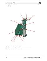
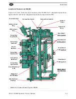
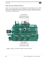
Mechanical set up of the 990-HB
5-19
KVAL 990-HB Operation / Service Manual
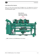
First clamp door against the stop that the machine is set-up for. Normally the back sec-
tion shifts away from the door stop that is being used. Also, depending what your
hinge locations are from the top of the door, down to the back section location will
vary from one machine to the next.
The standard set-up would be 2 inches of stop pin in both stop locations to equal 44
from the top to the center line of the lock bore.
NOTE:
Before changing the lock bore location, turn power OFF, as well as the air
supply at the slide valve located next to the back section valve bank where the air sup-
ply enters the back section. To change the lock bore location, you can add or subtract
pins to achieve the desired position to remove stop pins; for small adjustments, you
can simply change the bolt.
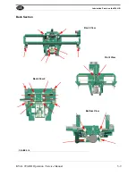
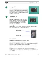
Setting Up Lock Bore Backset
The lock bore backset (the distance from the center line of the lock bore to the door's
edge) is controlled by four adjustable turret stops. KVAL's factory setting for the lock
bore turrets accommodates 5", 2.75" and 2.375".
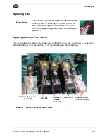
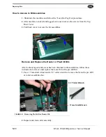
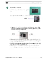
If No Auto Backset on 990-HB: Side Drill (Latch Hole)
The side drill bit has a 4-inch long fluted section. A 6-inch bit is necessary for backsets
and over-bored deadbolts. Be certain the machine is locked out electrically and the air
service is disconnected. Finally, wait until the bit has come to full stop before getting
out the collet wrenches.
NOTE:Be certain that the face plate router depth is correct and that the router chord is
fastened to the router as shown; otherwise, the long bit will eat the router.
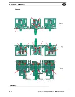
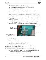
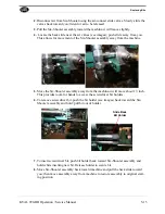
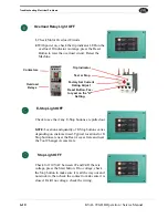
Lock Bore Diameter
Lock out air and electrical service. Use collet wrenches to put in the appropriate face
boring bit. Replace chip out block with a new one, or a block previously used for the
hole diameter.
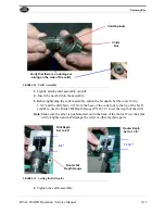
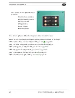
Plate Width: Plate Router Vertical Travel
Plate router vertical travel is established by rotating stop turrets like those found on the
hinge section. These turrets have four positions: set-ups for 1" and 1/8” for either
square edge or three-degree beveled edge. These bolts are color-coded:
• Red=1” square edge
• Blue=1-1/8” square edge
• Silver=1” beveled edge
• White=1-1/8” beveled edge
Notice that no change need be made to these turrets to change among doors of varying
thickness since the lock section centers the door when it clamps. If for some reason the
faceplate is not centered on the latch hole, you can adjust the screws that contact the
turret bolts. If both the plate and latch hole are off-center, contact KVAL for instruc-
Summary of Contents for 990-HB
Page 4: ...KVAL 990 HB Operation Manual ...
Page 25: ...Safety Sign Off Sheet 1 17 KVAL 990 HB Operation Service Manual ...
Page 26: ...Safety Sign Off Sheet 1 18 KVAL 990 HB Operation Service Manual ...
Page 66: ...Diagnostic Screen 2 40 KVAL 990 HB Operation Service Manual ...
Page 84: ...Calibration of the Back Section 3 18 KVAL 990 HB Operation Service Manual ...
Page 88: ...System IT Administration 4 4 KVAL 990 HB Operation Service Manual ...


