


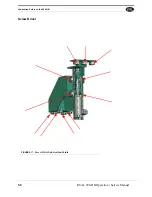
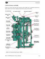
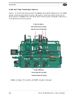
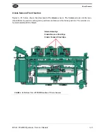
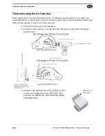
Mechanical set up of the 990-HB
5-17
KVAL 990-HB Operation / Service Manual
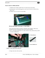
Setting Up the Hinge Backset
The hinge backset on the 990-HB is controlled by two positive stop bolts on each of
the three routing carriages.
• To adjust loosen the lock nut and adjust the bolt accordingly to give the right hinge
backset.
• Re-tighten the lock nut so that the bolt does not move out of place.
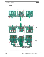
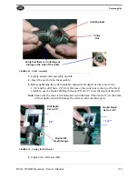
Setting the Doorstops
The 990-HB comes equipped with two door stops; one for right hand doors and one
for left hand doors. The doors stops accurately position the door so that the hinge loca-
tions are consistent.
With hinge centers set and the routers centered within the H-block, you are now ready
to set your door stops. Remember 990-HB always reference off of the top of the door.
Right-hand doors reference off of the left In-feed door stop. Left-hand doors reference
off of the right out feed door stop.
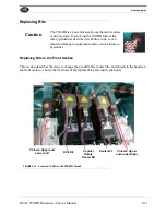
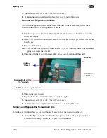
1.
To set you door stop use your specification from the top of the top hinge pocket to
the top of the door (7 inches in a 7-11 set-up).
2.
Machine door. Measure from the top of the door to the top of the hinge pocket. If the
pocket is less than 7 inches, move the stop away from the hinge router. If the pocket
is more than 7 inches, move the stop towards the hinge router.
3.
Loosen the door stop fastening bolts. Slide foreword or backward until the inboard
edge of the door stop is positioned 1 inch less than your specified dimension from
step 1.
4.
Tighten door stop fastening bolts.
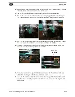
5.
Load a door, clamp it, and rout the hinge pockets into the door only.
6.
Measure your hinge centers, and the distance from the top of the pocket to the top of
the door. If hinge pocket locations are correct you can set-up your jamb stops. If
hinge centers are off, or the distance from the top of the pocket to the top of the door
is incorrect, re-adjust the door stops or “H” block locations before setting up your
jamb stops.
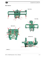
Back Section
Before setting up the back section you should test the various assemblies without bits
or cutters installed to ensure that everything is functioning properly.
1.
Remove the two drilling bits from both the lock bore and the side drills, and back
out the plate router so that it won't drag on the door edge and turn it off using the
router switch
2.
At the control panel turn on the lock bore and side drills and faceplate router, and
turn the back/front/both selector to back.
Summary of Contents for 990-HB
Page 4: ...KVAL 990 HB Operation Manual ...
Page 25: ...Safety Sign Off Sheet 1 17 KVAL 990 HB Operation Service Manual ...
Page 26: ...Safety Sign Off Sheet 1 18 KVAL 990 HB Operation Service Manual ...
Page 66: ...Diagnostic Screen 2 40 KVAL 990 HB Operation Service Manual ...
Page 84: ...Calibration of the Back Section 3 18 KVAL 990 HB Operation Service Manual ...
Page 88: ...System IT Administration 4 4 KVAL 990 HB Operation Service Manual ...


