background image

14

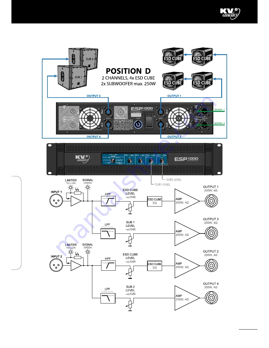
ESP1000 · Configuration - Position D

ESP1000  ·  C

onfigur

ation - P

osition D

Summary of Contents for ESP1000

Page 1: ...n is to constantly develop technologies that eliminate distortion and loss of information providing a true dynamic representation of the source Our aim is to create audio products that absorb you place you within the performance and deliver a listening experience beyond expectations ...

Page 2: ...n the loudspeaker has been damaged in any way such as when the power supply cord or plug has been damaged liquid has been spilled or objects have fallen into the loudspeaker rain or moisture has entered the loudspeaker the loudspeaker has been dropped or when for undetermined reasons the loudspeaker does not operate normally 16 Do not remove front or back panels Removal of the panel will expose ha...

Page 3: ... AC Power 4 Voltage requirements 5 The Power Connector 5 Current Requirements 5 Current Draw 6 AC Cable Colour Coding 6 Safety Summary 6 Features 7 Front Panel 7 Rear Panel 8 Specifications 9 Drawing 10 Configuration 11 Position A 11 Position B 12 Position C 13 Position D 14 Position E 15 Position F 16 Warranty Service 17 Notes 18 20 Contents ...

Page 4: ...ectable and it can be used to power any ESD units and other ranges of passive loudspeakers Whilst this unit is simple to operate improper use can be dangerous This is a very highpowered device that can output high voltages and sizeable currents Always use safe operating techniques with the ESP1000 FOR YOUR SAFETY READ THE IMPORTANT PRECAUTIONS SECTION AS WELL AS THE INPUT OUTPUT AND POWER CONNECTI...

Page 5: ...ical to the safe operation of the ESP1000 Cooling The ESP1000 has a comprehensive cooling system featuring chassis sealed PCB board mounting and shock mounted speed controlled fans This means that the cooling system never drives air across PCB boards connectors or components ensuring prolonged electronic component lifespan and minimizing maintenance cycles Air is drawn into the front of the amplif...

Page 6: ...age drops at the service entry The Power Connector The ESP1000 requires grounded outlets It is very important that the amplifiers AC supply be properly grounded in order to operate safely and properly Use the PowerCon AC cable wiring diagram overleaf to create international or special purpose power connectors Power connector assembly Current Requirements Each of the ESP1000 s power supply inputs r...

Page 7: ...e grounding mains receptacle The mains plug shall remain easy to operate The amplifier must be powered from the same phase as other interconnected powered units The receptacle must be connected to a fuse or circuit breaker Connection to any other type of receptacle poses a shock hazard and may violate local electrical codes Do not allow water or any foreign object to get inside the amplifier Do no...

Page 8: ...esent at the Input to that particular channel of the amplifier When yellow they indicate that the audio limiter has been activated for that particular channel of the amplifier 4 Power Thermal Protection These are dual colour LED s When green they indicate that the Power Switch is ON and that channel of the amplifier is powered up When red they indicate that channels has overheated and shut down Th...

Page 9: ...d The signal for the subwoofer is produced within the internal crossover Bridge Mono Mode has its own power output 3 PowerCon Power Connectors The ESP1000 accept standard PowerCon terminated AC Mains cables The ESP1000 uses one connector per two channels 4 Fans The cooling fans operate continuously while the ESP1000 is on An internal temperature sensor increases the speed of the fans during high t...

Page 10: ... RMS Out Power 8Ω bridged 500W RMS Signal Input Input Channels XLR Input Sensitivity 1 55V Input Impedance 20kΩ balanced Signal Output XLR Through Speaker Output Speaker Output Neutrik Speakon Features Level Control to 0dB Equalization Flat or according to the setup RMS Limiter YES Indicators Power ON Thermal RMS Limiter Signal Power Power Connector Neutrik PowerCon Operating Voltage 115V 230V 250...

Page 11: ...10 ESP1000 Drawing Drawing ESP1000 Drawing ...

Page 12: ...11 ESP1000 Configuration Position A ESP1000 Configuration Position A ...

Page 13: ...12 ESP1000 Configuration Position B ESP1000 Configuration Position B ...

Page 14: ...13 ESP1000 Configuration Position C ESP1000 Configuration Position C ...

Page 15: ...14 ESP1000 Configuration Position D ESP1000 Configuration Position D ...

Page 16: ...15 ESP1000 Configuration Position E ESP1000 Configuration Position E ...

Page 17: ...16 ESP1000 Configuration Position F ESP1000 Configuration Position F ...

Page 18: ...orized distributor service centre or shipped directly to the KV2 Audio factory Because of the complexity of the design and the risk of electrical shock all repairs must be attempted only by qualified technical personnel If the unit needs to be shipped back to the factory it must be sent in its original carton If improperly packed the unit may be damaged To obtain service contact your nearest KV2 A...

Page 19: ...KV2 Audio International Nádražní 936 399 01 Milevsko Czech Republic Tel 420 383 809 320 Email info kv2audio com www kv2audio com KVV120136 00 01 0 The Future of Sound Made Perfectly Clear ...

Reviews: