background image

15

A

B

D

R

C

16

A

B

C

17

18

B

C

A

A

B

C

D

E

20

22

21

A

B

D

E

C

S

19

Summary of Contents for KD935.2

Page 1: ...sungen GB Instructions for use and installation instructions Instructions d utilisation et avis de montage Gebruiksaanwijzing en montagehandleiding Istruzioni di uso e di montaggio Instrucciones de uso y de montaje Instruções de uso e de montagem F NL I E P ...

Page 2: ...e connected to the terminal in the plug which is marked with the letter E or by the earth symbol or coloured green or green and yellow the wire which English is coloured blue must be connected to the terminal which is marked with the letter N or coloured black the wire which is coloured brown must be connected to the terminal which is marked with the letter L or coloured red When making the electr...

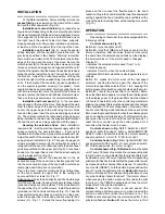
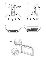
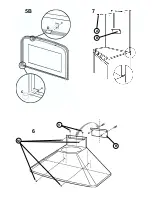
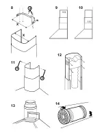
Page 3: ...ovided Fit the air deflector to the upper flue Fig 12 with 4 screws Install the reduction provided on the hood air outlet point Fig 13 Take the 2 assembled extension flues and set them on the hood extend the upper flue to the ceiling and secure with the 2 screws G Fig 11 Extend the lower flue taping it in place and then connect the flexible pipe to the hood reduction Pluginthehood Extendthelowerfl...

Page 4: ...ncandescent light bulbs remove the grease filters so as to be able to access the inside of the unit remove the screw securing the light fitting and then working from inside the hood push the light fitting pin towards the inside of the unit Replace with light bulbs of the same type Fig 22 if your appliance has the same kind of lights as in the figure 21 to replace theincandescent light bulbsopen th...

Page 5: ...1 2 3 4 A 5A C D ...

Page 6: ...6 B V M 5B C D A 7 B ...

Page 7: ...8 X X W A 9 10 11 G 12 13 14 G ...

Page 8: ...15 A B D R C 16 A B C 17 18 B C A A B C D E 20 22 21 A B D E C S 19 ...

Reviews: