background image

Gateway EtherCAT

6

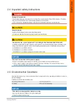
2.4 Important safety instructions

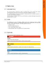
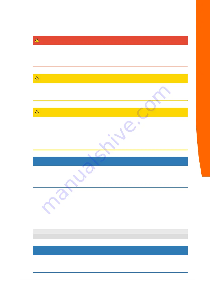
 DANGER

Danger of explosion

The modular Gateway component do not meet the requirements of the ATEX directive. Therefore,
they are not suitable for use in potentially explosive environments.

a) Do not use the modular Gateway component in potentially explosive environments.

 CAUTION

Electric shock

Switch off all voltages before assembly/disassembly.

a) Failure to observe this warning may result in personal injury.

 CAUTION

The devices are „open equipment“ according to the Standard UL61010-2-201.

To fulfill requirements for safe operation with regard to mechanical stability, flame retardation, sta-
bility, and protection against contact, the following alternative types of installation are specified:

a) Installation in a suitable cabinet.

b) Installation in a suitable enclosure.

c) Installation in a suitable equipped, enclosed control room.

NOTICE

Incorrect connection of the power supply

Using an unsuitable power supply can destroy your modules and connected devices.

a) Use a power supply in the approved area for the base modules. The values for this can be

found in the technical data of your base module.

2.5 Environmental Conditions

Operate the device only in an environment that corresponds to the operating conditions in order to
prevent damage.

Suitable environmental conditions are:

Operating temperature

-20 °C up to +55 °C

Humidity

93% (non-condensing)

NOTICE

This device is designed for indoor use only.

If you use the device outdoors, it may be destroyed.

a) Use the device indoors only.

Safe Use

Summary of Contents for PR100073

Page 1: ...User Manual Gateway EtherCAT 3 31 2022 ...

Page 2: ...tal Conditions 6 3 Overview 8 3 1 Functionality 8 3 2 Control Elements 9 3 3 Status LEDs 11 4 Installation 13 4 1 Preparations for Inteference free Operation 13 4 2 Requirements 14 4 3 Connecting Gateway Components 15 4 4 Installing a Gateway in the Control Cabinet 16 4 5 Connecting a Gateway to the Fieldbus 16 4 6 Connecting the Power Supply 17 5 Configuration 18 5 1 Supported Size of Process Dat...

Page 3: ...mark Protection KUNBUS is a registered trademark of KUNBUS GmbH Windows and Microsoft are registered trademarks of Microsoft Corp EtherCAT is a registered trademark and patented technology licensed by Beckhoff Automation GmbH Germany KUNBUS GmbH Heerweg 15 C 73770 Denkendorf Germany www kunbus com 1 2 Notes Regarding this User Manual This user manual provides important technical information that w...

Page 4: ...y qualified personnel damage is caused by technical modification to the product e g soldering 1 5 Customer Service If you have any questions or suggestions concerning this product please do not hesitate to contact us KUNBUS GmbH Heerweg 15 C 73770 Denkendorf Germany support kunbus com www kunbus com General Information ...

Page 5: ...d and put into operation by trained qualified personnel Before assembly it is absolutely essential that this documentation has been read carefully and understood Expertise in the following fields is assumed electronic circuits Basic knowledge of EtherCAT work in electrostatic protected areas locally applicable rules and regulations for occupational safety 2 3 Symbols The symbols used have the foll...

Page 6: ...ainst contact the following alternative types of installation are specified a Installation in a suitable cabinet b Installation in a suitable enclosure c Installation in a suitable equipped enclosed control room NOTICE Incorrect connection of the power supply Using an unsuitable power supply can destroy your modules and connected devices a Use a power supply in the approved area for the base modul...

Page 7: ...Gateway EtherCAT 7 Safe Use ...

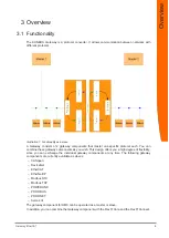
Page 8: ...e these gateway components as you wish This design offers you a high degree of flexibility since you can exchange the individual gateway components at any time The following gateway components are currently available as slaves CANopen DeviceNet EtherCAT EtherNet IP Modbus RTU Modbus TCP POWERLINK PROFIBUS PROFINET Sercos III The gateway component for DMX can be operated as a master or slave In add...

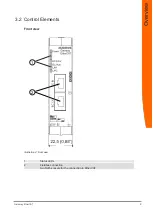
Page 9: ...Gateway EtherCAT 9 3 2 Control Elements Front view 1 2 Illustration 2 Front view 1 Status LEDs 2 Fieldbus connection two RJ45 sockets for the connection to EtherCAT Overview ...

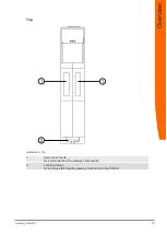
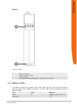
Page 10: ...Gateway EtherCAT 10 Top 1 1 2 Illustration 3 Top 1 Interconnect ports for interconnecting the gateway components 2 Locking clamps for securely attaching the gateway component to the DIN rail Overview ...

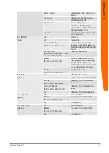
Page 11: ...ttaching the gateway component to the DIN rail 3 3 Status LEDs The gateway component is equipped with 5 status LEDs The LED Power provides information about the state of the gateway component The other LEDs provide information about the EtherCAT status LED State Meaning Power green red off Gateway component not run ning Overview ...

Page 12: ... ms on 1000 ms off Time limit exceeded flickers 50 ms on 50 ms off An error was detected during the starting process indicating that the status INIT was reached but a bit error was set in the Alarm Status Register flashes 200 ms on 200 ms off Configuration error EC RUN green off EtherCAT State Init or gateway component is off flashes 200 ms on 200 ms off EtherCAT State Pre Opera tional suddenly fl...

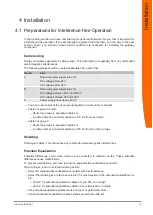
Page 13: ...ndles Cables of group A and B Route the groups in separate bundles or in cable ducts at a minimum distance of 10 cm from each other Cables of group C Route the groups in separate bundles or in cable ducts at a minimum distance of 50 cm from the other groups Shielding Shield your cables This will reduce any unintended electromagnetic interferences Potential Equalization Potential differences occur ...

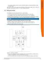
Page 14: ...e DIN rail horizontally in the control cabinet according to the manufacturers specifica tions Make sure that the Gateway module has sufficient distance to other devices NOTICE Your gateway could be damaged if temperatures are too high a Make sure that the ambient temperature in the control cabinet is less than 60 C b Keep the ventilation slots unobstructed These must not be covered by cables etc c...

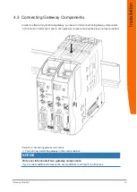
Page 15: ...nents a Connect an interconnect port to each gateway component using the plug in jumper provided Illustration 6 Connecting gateway components ð You can now install the gateway in the control cabinet NOTICE Only ever interconnect two gateway components If you connect additional components severe defects could result on all devices Installation ...

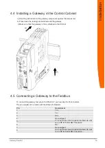
Page 16: ...ched to the DIN rail 4 5 Connecting a Gateway to the Fieldbus To connect the gateway component to EtherCAT you need two RJ45 connectors The pin assignment complies with the Ethernet standard Pin Assignment 1 TX 2 TX 3 RX 4 Not assigned Pin 4 and 5 are interconnected and laid via a fil ter on PE for better EMC response 5 6 RX 7 Not assigned Pin 7 and 8 are interconnected and laid via a fil ter on P...

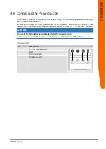
Page 17: ... supply for each gateway component and make sure that the GND are connected to each other at the power supply Connect FE to PE with low resistance NOTICE Connect the two gateway components to the power supply a Ensure in particular that no potential differences occur between the GND pins 2 Pin assignment Pin Assignment 1 24 V for module supply 3 1 2 4 2 GND 3 Do not connect 4 Functional earth Inst...

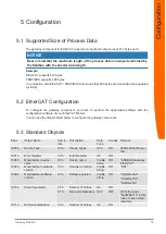
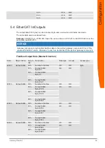
Page 18: ...of your EtherCAT Master You can use the objects listed below to configure the gateway component 5 3 Standard Objects Index Object Name Sub in dex Description Data Type Access Remark 1000 h Device Type 00 h Device Types U32 RO 0000 0000h No pro file 1001 h Error Register 00 h Error Register U8 RO 1008 h Manufacturer device name 00 h Device name Visible string RO KUNBUS Gateway EtherCAT 1009 h Manuf...

Page 19: ...RW U32 RW 80 h Assigned object 128 U32 RW 1A00h 1A03h Transmit PDO mapping 00 h Number of assigned objects U8 RW A mapping can con sist of up to 128 as signed objects It must not be greater than 128 bytes 01 h Assigned object 1 U32 RW 02 h Assigned object 2 U32 RW 03 h Assigned object 3 U32 RW 04 h Assigned object 4 U32 RW 05 h Assigned object 5 U32 RW 06 h Assigned object 6 U32 RW U32 RW 80 h Ass...

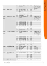
Page 20: ...artner gateway component Fieldbus Output Data Master Direction Index Object Name Sub in dex Description Data type Access Access type 2000 h Output Buffer 00 h Number of entries U8 RO Byte 01 h Output Buffer Byte 0 U8 RO 02 h Output Buffer Byte 1 80 h Output Buffer Byte 127 2001 h Output Buffer 00 h Number of entries U8 RO 01 h Output Buffer Byte 128 U8 RO 02 h Output Buffer Byte 129 80 h Output Bu...

Page 21: ...d 128 U16 RO 02 h Output Buffer Word 129 40 h Output Buffer Word 191 2013 h Output Buffer 00 h Number of entries U8 RO 01 h Output Buffer Word 192 U16 RO 02 h Output Buffer Word 193 40 h Output Buffer Word 255 2020 h Output Buffer 00 h Number of entries U8 RO Double word 01 h Output Buffer Double Word 0 U32 RO 02 h Output Buffer Double Word 1 20 h Output Buffer Double Word 31 2021 h Output Buffer ...

Page 22: ...ion Data type Access Access type 2100 h Input Buffer 00 h Number of entries U8 RW Byte 01 h Input Buffer Byte 0 U8 RW 02 h Input Buffer Byte 1 80 h Input Buffer Byte 127 2101 h Input Buffer 00 h Number of entries U8 RW 01 h Input Buffer Byte 128 U8 RW 02 h Input Buffer Byte 129 80 h Input Buffer Byte 255 2102 h Input Buffer 00 h Number of entries U8 RW 01 h Input Buffer Byte 256 U8 RW 02 h Input B...

Page 23: ...ord 128 U16 RW 02 h Input Buffer Word 129 40 h Input Buffer Word 191 2113 h Input Buffer 00 h Number of entries U8 RW 01 h Input Buffer Word 192 U16 RW 02 h Input Buffer Word 193 40 h Input Buffer Word 255 2120 h Input Buffer 00 h Number of entries U8 RW Double word 01 h Input Buffer Double Word 0 U32 RW 02 h Input Buffer Double Word 1 20 h Input Buffer Double Word 31 2121 h Input Buffer 00 h Numb...

Page 24: ...ponent by SDO entry in the OBD Index Object Name Sub in dex Description Data type Ac cess Remark 0x2200 Status of the partner gateway component 00 h Number of en tries U8 RO 01 h Length of the input data RO max 512 bytes 02 h Length of the output data U16 RO max 512 bytes 03 h Module Type U16 RO 74 EtherCAT Gateway Component 04 h Fieldbus Status U8 RO 0x00 Fieldbus not connected Check all connecti...

Page 25: ...ring operation cyclical data exchange 100 mA Status display LED Environmental Conditions Ambient temperature 30 C 55 C Storage temperature 30 C 60 C Humidity 93 at 40 C Condensing Not allowed Protection class Control cabinet Housing Terminal area IP54 IP20 IP20 Assembly data DIN rail 35 x 7 5 mm Height 96 mm Depth 110 4 mm Illustration 7 Side dimensions Technical Data ...

Page 26: ...Gateway EtherCAT 26 Illustration 8 Front dimensions Technical Data ...

Page 27: ...KUNBUS GmbH Gateway EtherCAT 27 ...

Page 28: ......

Reviews: