background image

FNL Getting Started

19 / 22

– After the selection of "Search and list all TCP Devices" (Key 9), enter

the number of the FNL to be used.

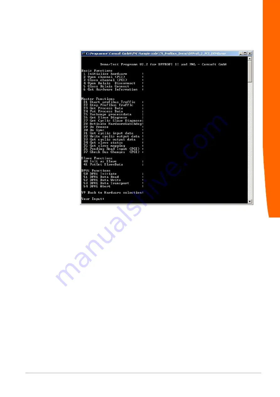
Illustration 24: 

Sample program: Scope of operation

Selection of the needed functions.

The DPV1-functions can be found from point 50 to 54. Detailed
Profibus-DPV1 information can be found in the provided manual
"DP_DPV1_E.pdf".

PROFIBUS

Summary of Contents for FNL Series

Page 1: ...Getting Started FNL 26 04 2016 ...

Page 2: ...Getting Started Table of Content 1 Introduction 3 1 1 Getting Started 3 1 2 FNL 3 2 Install 4 2 1 Install FNL 4 2 2 Install Software 4 3 Ethernet 5 3 1 Set TCP IP Adresse 5 3 2 Set operation mode 7 4 PROFIBUS 10 4 1 Master 10 4 2 Slave 20 ...

Page 3: ... well as DP Slave mode FNL can be directly operated via its TCP IP Socket Only a few simple commands are necessary to get FNL into operation Within scope of delivery a detailed Microsoft Visual C 6 0 example program incl C C source code can be found describing the implementation of the TCP IP Socket Interface Due to the independent access via the TCP IP Socket Interface FNL can be integrated into ...

Page 4: ...C used for the FNL configuration must be connected to the same Ethernet network as well A direct connection between the PC and FNL via an Ethernet cross cable is also possible 2 2 Install Software The delivered software on the CD needs to be installed on a Windows based PC Start the setup program and follow the instructions to install the software The setup program copies all necessary components ...

Page 5: ...Configurator from the Windows Start Menu KUNBUS GmbH Network Configurator The KUNBUS Network Configurator scans automatically the network and displays all detected FNL devices For scanning the network again click the search symbol on top left Illustration 1 KUNBUS Network Configurator Ethernet ...

Page 6: ... 6 22 Double click the FNL to be configured and adjust the IP address Subnet mask and Gateway Using DHCP to obtain the IP address automatically is possible as well Illustration 2 Adjustment of the TCP IP address Ethernet ...

Page 7: ...de FNL Mode FNL supports 2 operation modes to guarantee the downwards compatibility to existing applications Select the tab Advanced and adjust the parameter FNL Mode to KUNBUS interface Illustration 3 Adjustment of the FNL operation mode Ethernet ...

Page 8: ...he adjusted PROFIBUS address in DPAutoslaveAddress FNL will detect the PROFIBUS Baud rate automatically and accepts the I O configuration set by the PROFIBUS DP Master Illustration 4 FNL DPAutoSlaveMode This option is only available from firmware version 2 19 14 Please contact KUNBUS support if you need to update the firmware Ethernet ...

Page 9: ...utton to close the device properties dialogue box Network Configurator activates the changed parameters on the related FNL device and displays it Illustration 5 Abbildung 5 FNL with changed parameters Close the Network Configurator Ethernet ...

Page 10: ... it immediately with monitor modify and check possible errors A detailed description how to get up and running can be found in the online help system of the Configurator II Start the program Configurator II from the Windows Start Menu KUNBUS GmbH Profibus Configurator Create the PROFIBUS configuration download it to the FNL and test it with the monitor modify mode FNL stores the PROFIBUS configura...

Page 11: ...ection The installed FNL devices are displayed Illustration 8 Installed FNL device Select a FNL device and click the OK button If nothing is displayed click the Configure Ethernet Devices button to rescan the available FNL devices If still no FNL is found check your installation Refer to the online help system of CONFIGURATOR II for details of the driver selection Download the PROFIBUS DP configur...

Page 12: ...oad of PROFIBUS configuration Monitor Modify Mode With the Configurator II Monitor Modify mode the flashed PROFIBUS DP configuration can be tested immediately Please note that the configured DP Slaves must be connected to the FNL Click the Monitor Modify symbol in the toolbar of Configurator II Illustration 11 Monitor Modify symbol PROFIBUS ...

Page 13: ... Monitor Modify mode Configurator II displays the status of every DP Slave coloured frame and allows to monitor and modify the I O data and also display the PROFIBUS specific diagnostic data by clicking the DP Slaves For further details please refer to the online help system of Configurator II PROFIBUS ...

Page 14: ...oject can be directly loaded and compiled with Microsoft Visual C 6 0 The sample program is a 32 Bit console application focussing on the FNL programming interface Due to clearness reasons no graphical elements are implemented For immediately test and startup of the PROFIBUS network the Configurator II provides a full graphical very powerful monitor modify mode and many functions for data exchange...

Page 15: ... Sample program FNL reset Press a key to reset FNL Illustration 16 Sample program Start cyclic profibus traffic Press a key to start cyclic profibus traffic Illustration 17 Sample program Get current profibus configuration Press a key to get current profibus configuration PROFIBUS ...

Page 16: ...ave diagnostic information Illustration 19 Sample program start watchdog monitoring Press a key twice to start watchdog monitoring Illustration 20 Sample program Profibus Profibus exchange data Press a key successively to start the profibus exchange data In the sample program you can exchange data 10 times at most PROFIBUS ...

Page 17: ...FNL Getting Started 17 22 Illustration 21 Sample program Reset FNL Press a key to reset FNL Illustration 22 Sample program Exit sample program Press a key to exit sample program PROFIBUS ...

Page 18: ...mation can be found in the provided manual DP_DPV1_E pdf The sample program is located in the directory program files KUNBUS GmbH FNL Sample code CS_Profibus_Demo The project can be directly loaded and compiled with Microsoft Visual C 6 0 The sample program is a 32 Bit console application focussing on the FNL programming interface Start the sample program DFProfi_2_PCI_DEMO exe Illustration 23 Sam...

Page 19: ...ces Key 9 enter the number of the FNL to be used Illustration 24 Sample program Scope of operation Selection of the needed functions The DPV1 functions can be found from point 50 to 54 Detailed Profibus DPV1 information can be found in the provided manual DP_DPV1_E pdf PROFIBUS ...

Page 20: ...on the FNL programming interface Due to clearness reasons no graphical elements are implemented For the DP Slave configuration the PROFIBUS address and the DPAutoSlaveMode has to be set with the Network Configurator It is necessary to activate the DPAutoSlaveMode and set the DPAutoSlaveAddress PROFIBUS address of the FNL with the Network Configurator before starting this example see chapter 2 2 3 ...

Page 21: ... devices Enter the number of the FNL to be used Illustration 27 Sample program FNL reset Press a key to reset FNL Illustration 28 Profibus exchange data Press a key successively to start the profibus exchange data In the sample program you can exchange data 10 times at most PROFIBUS ...

Page 22: ...FNL Getting Started 22 22 Illustration 29 Sample program FNL reset Press a key to reset FNL Illustration 30 A Sample program Exit Sample program Press a key to exit sample program PROFIBUS ...

Reviews: