background image

- 20 -

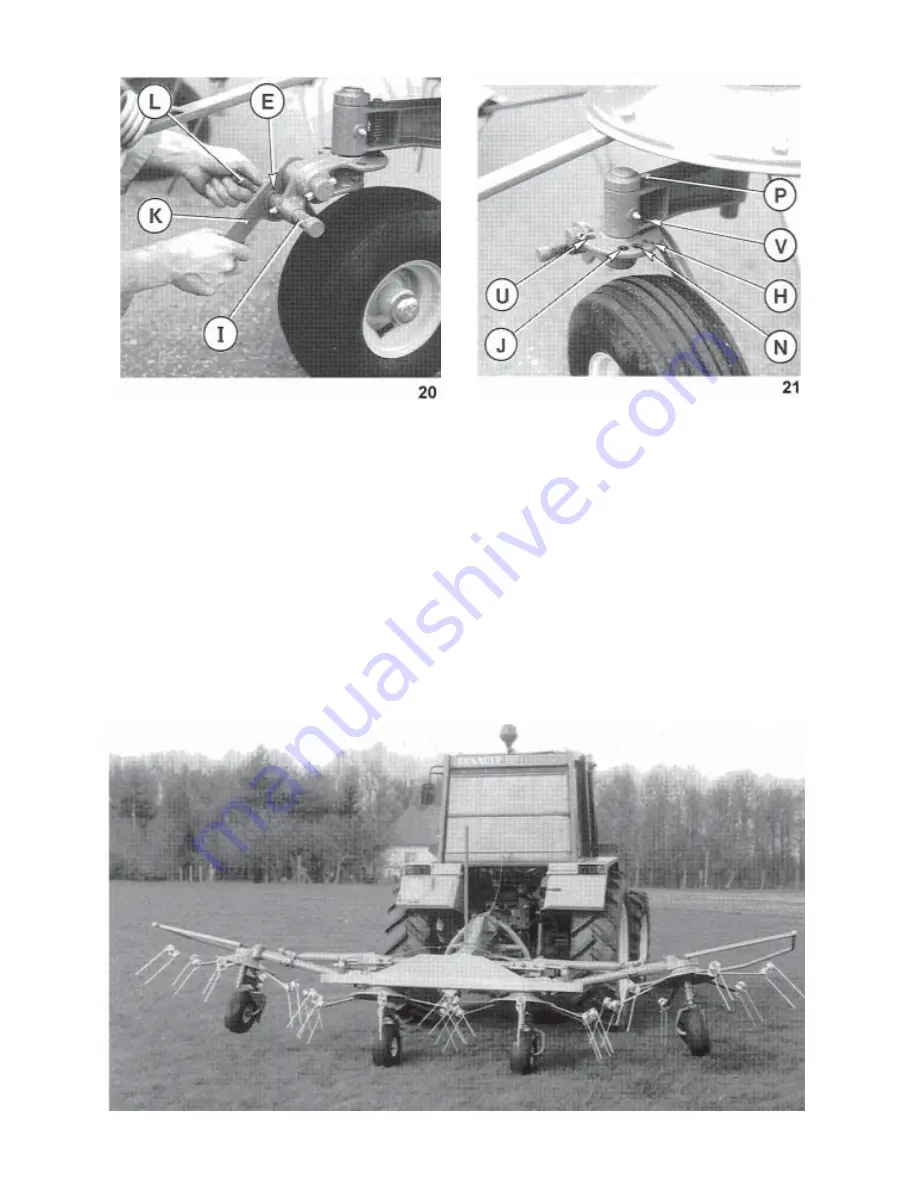
Adjustment of handle (L) with eccentric (E) (photo 20) is carried out as follows :

- Machine is attached to the tractor, stand in front of one of the rotors

- Pull eccentric (E) out of its housing and turn lever (L) 180° upwards or downwards

- Lift or lower handle (K) so that the eccentric (E) is in alignment with its housing and is re-engaged automatically

by return spring (I) (photo 20).

Proceed the same way on the remaining rotors.

Perfect rotor angle adjustment using tractor crank handle so that the tines lightly skim the ground at the front of

the machine.

When working along edges of fields, hedgerows, fences, etc., the oblique position is obtained by locking the

wheels in holes (H) to project the crop towards the left or holes (J) to project the crop towards the right (photo

21). Hole (N) corresponds to the regular work position (photo 21). Wheels are locked in the selected position by

means of locks (P) (photo 21). Positions (U) and (V) are never used on the 

GF 5001 MHA

 (photo 21).

If at the field ends the tractor does not lift the machine high enough to clear the outside rotors from the ground,

it is possible to lift the rotors slightly using the tractor hydraulic cylinders (see photo below).

Do not forget to put again the tractor 3 - point linkage in the free floating position.

Summary of Contents for GF 5001 MHA

Page 1: ...ASSEMBLY OPERATOR S MANUAL GF 5001 MHA GYROTEDDER PLEASE READ CAREFULLY BEFORE USING THE MACHINE N 95205 B GB 05 1999 ...

Page 2: ...l instruct you on the general operation of your machine He is interested that you get the best performance possible and will be glad to answer any special questions that may arise regarding the operation of the KUHN machine Your KUHN dealer can offer a complete line of genuine KUHN service parts These parts are manufactured and carefully inspected in the same factory that builds the machine to ass...

Page 3: ... 11 Assembly instructions 12 Attachment to the tractor 17 PTO shaft 18 Working position and adjustments 19 Operating speed 21 Transport position 22 Parking the machine 23 Lubrication 24 Optional accessories 25 Conditions of limited warranty 28 Copyright 1999 KUHN S A ...

Page 4: ...anufacturer Any use other than the designated operation is at the risk and responsibility of the operator Designated use of the machine also means following operation maintenance and repair recommendations given by the manufacturer using only genuine spare parts equipment and accessories as designated by the manufacturer The GF 5001 MHA Gyrotedder must only be operated maintained and repaired by c...

Page 5: ... work check the surrounding area beware of children Make sure there is sufficient visibility Keep all people and animals away from the danger zone of the machine risk of projection 8 Carrying people or animals on the machine when working or in transport is strictly forbidden 9 Machine must only be attached to tractor using means provided and in accordance with current safety standards 10 When atta...

Page 6: ...ne operating area 25 WARNING Danger of crushing and shearing can exist when components are operated by hydraulic or pneumatic controls 26 Before leaving the tractor or before adjusting maintaining or repairing the machine turn off the engine remove the ignition key and wait until all moving parts have come to a complete stop 27 Do not stand between the tractor and the machine unless the hand brake...

Page 7: ...O ensure that PTO speed rotational frequency and direction of rotation are in accordance with manufacturer s recommendations 9 Before engaging PTO keep all people and animals clear from the machine 10 Never engage PTO shaft when tractor motor is turned off 11 Never surpass the PTO angle recommended by the manufacturer 12 WARNING Rotating elements can continue turning momentarily after PTO is disen...

Page 8: ... sure to use hoses with the specifications and quality recommended by the manufacturer of the machine 6 Should a leak be found take all necessary precautions to avoid accidents 7 Any liquid under pressure particularly oil from hydraulics can penetrate the skin and cause severe injury If injured see a doctor immediately there could be danger of infection 8 Before any adjustments maintenance or repa...

Page 9: ...e or filters These must be given to waste disposal organizations to protect the environment 6 Disconnect power source before any work is done to the electric system 7 Check safety guards regularly particularly those that are subject to wear Replace immediately if damaged 8 Spare parts used must be in accordance with specifications and standards as defined by the manufacturer Use only genuine KUHN ...

Page 10: ...DATIONS When changing the machine over from the work to the transport position or vice versa danger of crushing and shearing can exist Be especially careful and keep all persons away from vicinity of the machine when maneuvering ...

Page 11: ...CED ON YOUR MACHINE IN THE AREAS INDICATED THEY ARE INTENDED FOR YOUR PERSONAL SAFETY AND FOR THE SAFETY OF THE PEOPLE WORKING WITH YOU THE TEXT SHOWN ON THEM GIVES THEIR PRECISE MEANING ENSURE THAT THESE PICTORIALS ARE ALWAYS LEGIBLE IF THEY ARE NOT REPLACE THEM ...

Page 12: ... 10 ...

Page 13: ...11220 5 00 m 16 7 Width in working position 5 43 m 17 9 Transport width 2 84 m 9 2 Length in transport position 2 31 m 7 7 Length in working position 2 31 m 7 7 Power requirement 15 kW 20 hp Weight with PTO 545 kg 1200 lbs Tyres 15 x 6 00 6 Tyre pressure 2 bars 29 psi ...

Page 14: ...pendulum arm to plate R with rope grip W as shown in photo 1 Adjust wire rope length so that it is slightly tensioned when the outside rotors are lifted into transport position Cut off surplus rope 2 Fitting the 3 point frame fig 2 Attach the 3 point frame C to the box type frame P by means of the vertical pivot pin A and secure in place with roll pins E 5 x 50 mm and E 8 x 50 mm as shown in figur...

Page 15: ...e shield T to reflector supports 1 using 4 hexagon screws V M 8 x 20 4 plain washers diameter 9 x 18 x 1 5 and 4 self locking nuts M 8 Also attach to box type frame P using 1 hexagon screw W M 8 x 12 and 1 lock washer M 8 6 Fitting the wheels photo 6 Fit the pre assembled wheels G into their holders F Place a shim washer I dia 35x45x2 5 ontop of the holder Then install shim washer K dia 35 x 50 x ...

Page 16: ...tines F on the tine arms B in such a way that the pressure from the tines closes the spiral the tines are facing in the direction of rotation of the rotors fig 8 Position the deflectors D Fit the screws A position washers C then tighten the self locking nuts E fig 8 to a torque of 16 daNm 120 ft lbs During the first few hours of work make frequent checks of tine nut and bolt tightness If necessary...

Page 17: ...the upper hole of support plate C then through plate P and tie a knot Thread the other end of cord through handle A and tie a knot at desired length so that locks can easily be maneuvered from the tractor seat Cut off surplus cord at the knot and fit plug into handle A To avoid that cords are too lax above the machine tie a knot N in the cord just before support plate C Then install the hydraulic ...

Page 18: ...ers M 10 and 2 nuts M 10 as shown in figure 10 Ensure that safety guard mounting studs are positioned at the front of this support Tighten hexagon bolts to 5 daNm 37 ft lbs Push both guards 6 onto support 7 and secure them with 4 hexagon bolts 12 M 8 x 45 and nuts M 8 photo 10 Torque to 3 daNm 20 ft lbs Side guards 5 are fitted to outside housings 11 using 2 hexagonal head bolts 1 M 12 x 60 and 2 ...

Page 19: ...d on the outside for Cat II tractors In the latter case use the 25 mm diameter link pins to attach tractor top link Q to the pendulum arm A photo 11 The pendulum arm has three attachment positions to suit varying tractor top link lengths Connect hydraulic hose E to a female hydraulic connection at the rear of the tractor photo 11 When the machine is attached to the tractor raise stand D and secure...

Page 20: ...must be maintained If this is not the case shorten the two transmission tubes and the two guard tubes by the same length fig 13 and 14 Bevel and clean the tubes fig 15 and grease the inside of the outer tube fig 16 3 Never operate the PTO at too great an angle 30 maximum These recommendations and adjustments must be respected to avoid damage or premature wear of the PTO Never connect the PTO to th...

Page 21: ...ion photo 17 When tedding the tractor 3 point linkage should always be in the free floating position NEVERENGAGETHETRACTORPTO WHEN THE OUSIDE ROTORS ARE FOLDED INTO TRANSPORT POSI TION Rotor angle is adjustable in 2 different positions 1 Maximum working angle is obtained when handle L is facing upwards photo 18 2 Minimum working angle is obtained when handle L is facing downwards photo 19 Maximum ...

Page 22: ...ront of the machine When working along edges of fields hedgerows fences etc the oblique position is obtained by locking the wheels in holes H to project the crop towards the left or holes J to project the crop towards the right photo 21 Hole N corresponds to the regular work position photo 21 Wheels are locked in the selected position by means of locks P photo 21 Positions U and V are never used o...

Page 23: ...e speed is approximately 7 8 km hr 4 1 2 5 mph Second time over the speed can reach 10 12 km hr 6 1 2 7 mph according to the moisture content If the hay is dry the speed rotational frequency of the rotor should be reduced When the crop is very long heavy and wet the forward speed should be reduced In difficult conditions such as these it is generally advisable to lower the forward speed and increa...

Page 24: ...it for all movement to stop Pull cord C photo 22 Activate the tractorhydraulicsandlifttheouterrotors until locks R automatically lock into the transport position photos 22 and 23 This operation locks the pendulum arm simultane ously Double check that parking stand D is locked in its upper position with the spring cotter pin O photo 22 NEVER ENGAGE THE TRACTOR PTO WHILE THE MACHINE IS IN THE TRANSP...

Page 25: ...sitioned in its support S to avoid ground contact which could result in premature failure due to contamination with dirt and dust photo 24 Put male coupling of the hydraulic hose F into its parking support H photo 24 IFEVERTHEGF5001MHAISTOBEPARKEDWHILSTINITSTRANSPORTPOSITION ANAREA MUSTBEUSEDWHERETHEGROUNDISVERYEVENANDLEVEL WEDGESMUSTALWAYS BE PLACED UNDER THE 2 CENTRAL WHEELS photo 24 24 ...

Page 26: ...oto 18 the four levers H photo 18 page 13 and all other pivoting points of the machine Once a year The four rotor gearboxes G photos 25 and 25 A The drive gearbox is filled with SHELL Multi Purpose grease NLGI grade 2 capacity 0 8 kg Check the amount once a year by removing the rear cover J photo 1 A page 12 Lubricate the following points with SHELL OIL Once a week the four wheel position locks th...

Page 27: ...uction gearbox proceed as follows Fit guard G photo 28 on Duplex reduction gear box using the hardware provided therefore Remove original PTO shaft guard from the central gearbox Slide the Duplex reduction gearbox unit Q on the drive shaft from the central gearbox R and secure in place with 2 self locking screws S M 12 x 40 and 2 spring washers torque 9 daNm 65 ft lbs Fit the retaining ring 35 E d...

Page 28: ...facing in the right direction fig 29 On machines marketed in Switzerland the 4 yellow and black stickers supplied with the set must be affixed to the signal panels 12 in place of the red and white stickers Fit front lights A on the front side of the warning boards 12 slit E is facing down photo 30 Fit right rear light D marked R onto the rear side of the right warning boards photo 31 Fit left rear...

Page 29: ... 176 mm photo 32 Attach support P of plug O to the 3 point pendulum arm guard with 2 hexagon screws H M 6 x 30 and 2 self locking nuts M 6 as shown in photo 32 For the lighting equipment to function a 7 pin socket is required at the rear of the tractor Place plug O in support P when detaching machine from tractor photo 32 ...

Page 30: ...ethods of testing Annex to AIC 1896 117 REV February 1988 Health and Safety Executive The method employed corresponds to the method No 4 in this document Unspecified testing conditions comply with ISO 5131 standard Measuring equipment conforms to NF S 31 009 standard The tractor used has a power of 59 kW A weighted emission sound pressure level L A eq inside tractor cab with closed windows Tractor...

Page 31: ...f it has been misused neglected or damaged by accident or let out on hire Nor can claims be accepted if parts other than those manufactured by us have been incorporated in any of our equipment Furthermore the Company shall not be responsible for damage in transit or handling by any common carrier and under no circumstances within or without the warranty period will the Company be liable for damage...

Page 32: ...sions on all questions as to defect and to the exchange of any part or parts That all safety instructions in the Operator s Manual shall be followed and all safety guards regularly inspected and replaced where necessary No warranty is given on second hand products and none is to be implied Persons dealing in the Company s products are in no way legal agents of the Company and have no right or auth...

Page 33: ... N O T E S ...

Page 34: ......

Page 35: ...ctive The Operator should respect all Health and Safety regulations as well as the Highway Code For your own safety use only genuine KUHN spare parts The manufacturer disclaims all responsibilities due to incorrect use or non compliance with the recommendations given in this manual ...

Page 36: ...Fabriques F 67706 SAVERNE CEDEX FRANCE Tél 33 0 3 88 01 81 00 Fax 33 0 3 88 01 81 03 www kuhnsa com E mail info kuhnsa com Société Anonyme au Capital de 19 488 000 Euros For your safety and to get the best from your machine use only genuine KUHN parts ...

Reviews: