


2-M11
ZD21N-EC, ZD21-EC, ZD28-EC, WSM
TRANSAXLE
■
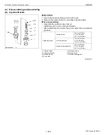
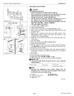
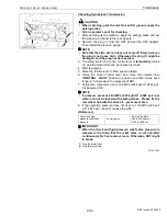
Regulator Valve
This machine is controlled with the regulator valve so
that the oil sent from the hydraulic pump may become the
setting pressure. And the oil flows into PTO clutch and
hydrostatic transmission.
(Reference)
• Regulator valve setting pressure: 0.50 to 0.69 MPa
5.0 to 7.0 kgf/cm
2
71.1 to 99.6 psi
W1014232
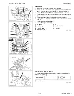
■
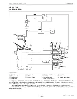
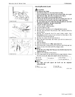
PTO Clutch “Engaged”
When the PTO clutch lever is set at the “Engaged”
position, the PTO clutch valve (6) rotates and form the oil
line to the PTO clutch pack.
Oil entering the clutch pack pushes the clutch piston
(5) to engage the clutch pack.
W1014380
■
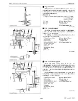
PTO Clutch “Disengaged”
When the PTO clutch lever is set at the
“Disengaged” position, the PTO clutch valve (6) rotates
and close the oil passage to the PTO clutch pack. The
oil in the PTO clutch pack drained into the transmission
case (5). Thus the clutch piston (2) is pushed back by
the spring (9).
When the piston (2) is pushed back, the piston push
to the brake pressure plate (1) so as to stop the rotation
and drag of the PTO shaft (4).
W1014560
(1) Poppet
(2) Spring
(3) Plug
(A) From Hydraulic Pump
(B) To Hydrostatic
Transmission
(C) To Transmission Case
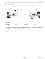
(1) Brake Pressure Plate
(2) Clutch Piston
(3) Clutch Gear
(4) Clutch Shaft (PTO Shaft)
(5) Transmission Case
(6) PTO Clutch Valve
(7) Poppet
(8) Clutch Spline Boss
(9) Spring
(10) Brake Disc
(A) From Hydraulic Pump
(B) To Hydrostatic
Transmission
(C) To Transmission Case
(1) Brake Pressure Plate
(2) Clutch Piston
(3) Clutch Gear
(4) Clutch Shaft (PTO Shaft)
(5) Transmission Case
(6) PTO Clutch Valve
(7) Poppet
(8) Clutch Spline Boss
(9) Spring
(10) Brake Disc
(A) From Hydraulic Pump
(B) To Hydrostatic
Transmission
(C) To Transmission Case
KiSC issued 09, 2006 A
Summary of Contents for ZD21-EC
Page 1: ...ZD21N EC ZD21 EC ZD28 EC WORKSHOP MANUAL ZERO TURN MOWER KiSC issued 09 2006 A ...
Page 7: ...5 ZD21N EC ZD21 EC ZD28 EC WSM SAFETY INSTRUCTIONS KiSC issued 09 2006 A ...
Page 8: ...6 ZD21N EC ZD21 EC ZD28 EC WSM SAFETY INSTRUCTIONS KiSC issued 09 2006 A ...
Page 11: ...9 ZD21N EC ZD21 EC ZD28 EC WSM DIMENSIONS DIMENSIONS KiSC issued 09 2006 A ...
Page 12: ...G GENERAL KiSC issued 09 2006 A ...
Page 59: ...1 ENGINE KiSC issued 09 2006 A ...
Page 60: ...CONTENTS MECHANISM 1 FUEL SYSTEM 1 M1 1 GOVERNOR 1 M1 KiSC issued 09 2006 A ...
Page 138: ...2 TRANSAXLE KiSC issued 09 2006 A ...
Page 178: ...3 FRONT AXLE KiSC issued 09 2006 A ...
Page 179: ...CONTENTS MECHANISM 1 STRUCTURE 3 M1 KiSC issued 09 2006 A ...
Page 187: ...4 HYDRAULIC SYSTEM KiSC issued 09 2006 A ...
Page 202: ...5 ELECTRICAL SYSTEM KiSC issued 09 2006 A ...
Page 205: ...5 M2 ZD21N EC ZD21 EC ZD28 EC WSM ELECTRICAL SYSTEM ZD28 KiSC issued 09 2006 A ...
Page 206: ...5 M3 ZD21N EC ZD21 EC ZD28 EC WSM ELECTRICAL SYSTEM ZD21N ZD21 KiSC issued 09 2006 A ...
Page 207: ...5 M4 ZD21N EC ZD21 EC ZD28 EC WSM ELECTRICAL SYSTEM ZD28 KiSC issued 09 2006 A ...
Page 237: ...6 ROTARY MOWER KiSC issued 09 2006 A ...
Page 238: ...CONTENTS MECHANISM 1 POWER TRANSMISSION 6 M1 2 LIFTING MECHANISM 6 M2 KiSC issued 09 2006 A ...


