background image

86

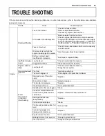
TROUBLE SHOOTING

Hydraulic 
System

Lift arms, bucket, 
drive unit power is 
too low.

Hydraulic oil level too low

* Add oil.

Leakages of hoses and / or 
joints

* Replace hose or joint.

Armrest is in "Raised" position.
Operator is not in the operator's 
seat.
Hydraulic unlock lever is not 
pressed.

* Lower the armrests.
* Sit in the operator's seat.

* Press the hydraulic unlock switch.

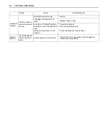
Electric 
system

" " mark appears 
in the instrument 
panel.

Electric system is malfunction.

* Check the error code number of next page and 
   contact your local dealer.

Trouble

Cause

Countermeasure

Summary of Contents for R065

Page 1: ...alaysia KUBOTA MALAYSIA SDN BHD No 3 Jalan Sepadu 25 123 Taman Perindustrian Axis Seksyen 25 40400 Shah Alam Selanɡor Darul Ehsan Malaysia Telephone 60 3 736 1388 Philippines KUBOTA PHILIPPINES INC 232 Quirino Hiɡhway Baesa Quezon City 1106 Philippines Telephone 63 2 422 3500 Taiwan SHIN TAIWAN AGRICULTURAL MACHINERY CO LTD 16 Fenɡpinɡ 2nd Rd Taliao Shianɡ Kaohsiunɡ 83107 Taiwan R O C Telephone 88...

Page 2: ...mung GERMANY German Institute for Standardization European Standard Falling Objects Protective Structures Hydrostatic Transmission International Organization for Standaridization Japanese Industry Standard Militaly Standard Roll Over Protective Structures Revolutions Per Minute Revolutions Per Second Society of Automotive Engineers USA Slow Moving Vehicle ABBREVIATION LIST R065 English Australia ...

Page 3: ...lock As a guide to the operation of your machine various universal symbols have been utilized on the instruments and controls The symbols are shown below with an indication of their meaning Horn Read the Operating Instructions Wiper washer Engine Warning Display Selector User Setting Low beam Clearance Light Working Light Set Clock Water separator fill up High Travel Speed Neutral Differential Loc...

Page 4: ...It will give you long satisfactory service To obtain the best use of your wheel loader please read this manual carefully It will help you become familiar with the operation of the wheel loader and contains many helpful hints about wheel loader maintenance It is KUBOTA s policy to utilize as quickly as possible every advance in our research The immediate use of new techniques in the manufacture of ...

Page 5: ...AILY CHECKS 9 CHECKING THE SWITCHES 9 Parking Brake Switch 9 Starter Switch 10 Horn Switch 10 Turn Signal Switch 10 High Low Beam Changing Switch 10 Headlight Switch 11 Hazard Lamp Switch 11 Attachment Unlock Switch 11 Differential Lock Switch 12 Display Selector Switch 12 Battery Charge Indicator 14 Engine Oil Pressure Indicator 15 Grow Plug Indicator 15 LCD for Normal Operation 16 LCD for Warnin...

Page 6: ...HE OPERATOR 30 WORKING IN THE VICINITY OF OVERHEAD POWER LINES 30 RUNNING IN OF THE MACHINE 30 Do not Work with Full Engine Rpm s or Full Loads during the First 50 Working Hours 30 Oil Change in the Run in Stage 30 STARTING 31 Adjusting the Operator s Seat 31 Seat Belt 32 Tilt Steering Adjustment 32 TRAVELING 33 Starting 33 Accelerator Pedal 33 Inching and Brake Pedals 34 Neutral Switch 34 Directi...

Page 7: ...cking coolant level and replenishing 61 Checking and replenishment of oil in the brake fluid reservoir 61 Grease fittings 62 Checking tire pressure wear and wheel nuts 63 Checking and cleaning the radiator and oil cooler 63 Checking the steering 63 Checking Gear Locked Parking Brake 64 Checking the disc brake 64 Checking and cleaning engine and electrical wiring 64 Checking V belt 64 Washing whole...

Page 8: ...suction filter 74 Replacing air cleaner element 75 EVERY 1500 SERVICE HOURS 76 Checking Injector Tip 76 EVERY 2000 HOURS SERVICE 76 Checking alternator and starter motor 76 EVERY 3000 SERVICE HOURS 76 Checking Injection Pump 76 ANNUAL SERVICE 76 Checking electrical leads and terminals 76 BIENNIAL SERVICE 76 Replacing fuel hoses and clamps 76 Changing coolant 77 Replacing Intake Air line 77 Replaci...

Page 9: ...CONTENTS SERVICE HOUR METER 89 ...

Page 10: ......

Page 11: ...ure If any component is damaged replace it Do not attempt repairs If ROPS is loosened or removed for any reason make certain all parts are reinstalled correctly 6 Do not install any attachments including water and calcium chloride that is added into the tires that exceed the specified maximum weight shown under MAXIMUM GROSS MACHINE WEIGHT space on the ROPS label 7 Do not start or operate an unsaf...

Page 12: ...t and attachment to the ground A Release the hydraulic pressure in the hydraulic system by operating the appropriate control levers For machines with mechanical quick coupler A Lock all control levers in neutral A After changing the front attachment make sure the installed attachment is securely attached to the quick coupler 15 To mount a fire extinguisher use the space above the fender on the sid...

Page 13: ...ee Tire pressure in TIRES in PERIODIC SERVICE section A Check tire pressure before commencing day to day operations A Do not use any liquids in the tires A Replace excessively worn tires with new tires before commencing operations A Only use identical wheels and tires with the same degree of wear on the same axle A Never exceed the specified max load capacity A Only use KUBOTA approved buckets pal...

Page 14: ...ssible If you do not follow these instructions the machine can go out of control and tip over 16 Avoid turning on a slope 17 Never perform digging or shoveling with the machine in the articulated condition or the machine may tip over 18 Never dig or shovel at high speed Such operation can cause the machine to lose stability and its rear wheels to lift off the ground which may lead to serious perso...

Page 15: ...s and traffic signs 7 Use the brake when the machine begins to accelerate by itself 8 If the engine should stall on a slope apply the brake to hold the machine in its present position and then lower the bucket to the ground and attempt to restart the engine 9 When operating over an obstacle such as a rock cross slowly at a right angle Trying to cross over it diagonally or at high speed may tip the...

Page 16: ...Stop the engine A Lower the bucket and attachments to the ground A Release the hydraulic pressure in the hydraulic system by operating the control levers Lock all control levers in neutral A Remove the key 6 SAFE LOADING AND TRANSPORT 1 When loading or unloading the machine on or from a truck or trailer be sure to use strong ramps Never use wet lumber etc 2 Keep the ramps at an angle such that the...

Page 17: ...n the hydraulic system by operating the control levers For details refer to HOW TO RELEASE PRESSURE TRAPPED IN THE HYDRAULIC SYSTEM A Lock all control levers in neutral A Remove the key 2 Never be under the machine while it is being lifted with only the bucket If servicing or checking underneath support it firmly with strong jackstands 3 Secure the articulated steering with the steering frame lock...

Page 18: ...und cable last See STARTING WITH AN AUXILIARY BATTERY in the OPERATING OF THE ENGINE section 13 Do not use or charge batteries whose electrolyte level is under minimum If you do the battery could be destroyed or the battery could explode Always keep the electrolyte level between the minimum and maximum level 14 Never remove the engine hydraulic oil plug or the radiator cap right after the engine h...

Page 19: ... in case of an emergency 1 Before towing 1 1 To release the negative brake loosen the 2 bolts on the rear axle cover and remove the spacer 1 2 Tighten both bolts by hand until both are in contact the internal pusher plate After tightening both bolts alternatively for a quarter of turn on each side with a wrench until they are completely tightened 1 3 Remove the caps of the 2 high pressure relief v...

Page 20: ...1 If you have questions about the correct disposal or storage of refuse and toxic waste contact your KUBOTA dealer or a local waste management contractor 22 Do not open high pressure fuel system High pressure fluid remaining in fuel lines can cause serious injury Do not disconnect nor attempt to repair fuel lines sensors or any other components between the high pressure fuel pump and injectors on ...

Page 21: ...ean out all accumulated flammable debris such as leaves straw pine needles branches bark small wood chips and any other combustible materials from inside the machine belly pans or lower unit structures as well as from area in proximity to the engine A Inspect all fuel lines and hydraulic hoses for wear or for deterioration Replace them immediately if they begin to leak A Examine electrical wiring ...

Page 22: ...SAFE OPERATION 12 8 DANGER AND WARNING LABELS ...

Page 23: ... 13 SAFE OPERATION ...

Page 24: ...SAFE OPERATION 14 ...

Page 25: ... 15 SAFE OPERATION ...

Page 26: ...SAFE OPERATION 16 ...

Page 27: ...dry with a soft cloth 3 Replace damaged or missing danger warning and caution labels with new labels from your local KUBOTA dealer 4 If a component with a danger warning and caution label affixed is replaced with new part make sure a new label is attached in the same location as the replaced component 5 Mount new danger warning and caution labels by applying on a clean dry surface and pressing any...

Page 28: ......

Page 29: ...wever apply if the product has not been handled according to the instruction given in the Operator s Manual even it is within the warranty period The Product s described in this Operator s Manual are designed and manufactured only for the country in which they are initially wholesaled by KUBOTA or one of its affiliated companies Neither KUBOTA Corporation nor its affiliated companies provide warra...

Page 30: ...SERVICING OF WHEEL LOADER 2 1 Engine serial No ...

Page 31: ...ing load straight ISO 14397 1 kg 2825 3000 Tipping load full turn ISO 14397 1 kg 2475 2625 Rated operating capacity ISO 14397 1 kg 1235 1310 Lifting capacity at ground level kN 26 2 Breakout force ISO 14397 2 kN 36 3 Fork Tipping load full turn ISO 14397 1 kg 2000 2120 Rated operating capacity SAE J1197 48 in tines kg 1200 1270 Traveling Drive system 4 WD Tire 12 5 18 Traveling speed Forward km h ...

Page 32: ...TED CONTENTS 1 Lift arm 2 Bell crank 3 Bucket 4 Front wheel 5 Rear wheel 6 Bucket cylinder 7 Lift cylinder 8 ROPS FOPS CANOPY 9 ROPS FOPS CABIN 10 Headlight 11 Turn signal light Clearance light 12 Working light 13 Fuel tank cap 14 Lift arm support 15 Rearview mirror ...

Page 33: ...5 DESCRIPTION OF MACHINE PARTS DEPICTED CONTENTS 16 Towing pin 17 Rear combination light Turn signal Tail light Brake light Back light 18 Rear working light option 19 Rotary beacon option ...

Page 34: ... 7 Headlight switch 8 Attachment unlock switch 9 Direction switch 10 Speed control switch down 11 Speed control switch up 12 Neutral switch 13 Starter switch 14 Electrical outlet 15 Engine stop knob 16 Differential lock switch Cabin type only 2 Front wiper Washer switch Refer to page 21 17 Beacon light switch 18 Working light switch 19 Rear Wiper Washer switch 20 Blower switch 21 Temperature contr...

Page 35: ...nd Levers DEPICTED CONTENTS 1 Steering wheel 2 Multi function operating lelver control lever 3 Control lever lock 4 Auxiliary port lever 5 Auxiliary port lever lock 6 Engine speed control knob 7 Inching and brake pedal 8 Accelerator pedal Option 9 Brake pedal ...

Page 36: ...gauge 7 Warning indicator 8 Engine warning indicator 9 Speed mode indicator 10 LCD 11 Forward backward and neutral indicator 12 Periodic check indicator 13 Hazard Turn signal indicator 14 Parking brake indicator 15 Differential lock indicator 16 Headlight high beam indicator 17 Headlight low beam indicator 18 Clearance light indicator 19 Fuel gauge 20 Fuel stock indicator 21 HST oil temperature wa...

Page 37: ...heck dust indicator of air cleaner See DAILY CHECK in PERIODIC SERVICE section A Check all control lamps indicators and hour meter A Check the light system A Check the seat belt and the ROPS FOPS safety device A Check the condition of the safety and warning labels See DANGER AND WARNING LABELS in SAFE OPERATION section CHECKING THE SWITCHES BParking Brake Switch The parking brake is to be used whe...

Page 38: ...er words once the engine has started be sure to free the key BHorn Switch Even when the starter key is in STOP position the horn will be beeped by pressing the horn switch BTurn Signal Switch Operate the turn signal switch to the right or left according to the direction in which the machine is to be turned The corresponding turn signal will blink Be sure to return the switch to the center position...

Page 39: ...ight and to the second position to turn on the headlight low beam BHazard Lamp Switch Press the hazard lamp switch for the hazard lamps to blink BAttachment Unlock Switch The attachment unlock switch is applied for hydraulic quick coupler This switch must be applied for safety reason when the attachment locking shall be unlocked The quick coupler is ready for unlocking only while the switch is dep...

Page 40: ...or highway If one of the wheels should slip release the accelerator pedal and press the differential lock switch Both wheels will turn together then reduce slippage Differential lock is available only while the switch is depressed A The differential lock switch can not be activated at high speed mode BDisplay Selector Switch Press the display selector switch The electronic meter s LCD will change ...

Page 41: ...etting request indicator on the instrument panel is blinking Setting the month Press user setting switch and the numeric setting will be smaller Press display selector switch and the numeric setting will be larger Setting the day Press user setting switch and the numeric setting will be smaller Press display selector switch and the numeric setting will be larger Changing the AM PM system to the 24...

Page 42: ...r requesting the setting the clock BBattery Charge Indicator This warning indicator lights up if the charging system fails with the engine running When the starter switch is turned to RUN with the engine off the indicator lights up and when the engine starts the indicator goes out If the indicator stays on with the engine running stop the engine and check the fan belt A If there is disconnection o...

Page 43: ...the following symbol will appear BGrow Plug Indicator With the starter key at the RUN position the engine s preheat status is indicated A When the starter switch is turned to the RUN position the engine will be preheated for a given period of time and the indicator will turn on A The above indication appears momentarily when the engine is started but it does not indicate trouble This is because th...

Page 44: ...With the starter key at the STOP position press the fuel level audible indication buzzer and the fuel level can be checked with buzzer sound 2 Start refueling the machine The buzzer beeping intervals vary according to how much fuel is poured into the tank As the machine becomes filled up the buzzer sounds almost continuously 3 While refueling the machine listen to the buzzer sound to know how much...

Page 45: ...hts up due to failure of the lubricating system with the engine running When the starter key is turned to RUN position with the engine off this engine oil pressure warning indicator lights up warning indicator blinks and when the engine starts the indicators go out If the indicator stays on with the engine running stop the engine and check the engine oil level C Battery charge indicator This batte...

Page 46: ...r inform you of details concerning care and maintenance C Overheat warning If the coolant temperature becomes elevated the coolant temperature indicator blinks and the warning message E 9114 appears on LCD as long as the temperature remains elevated If the coolant temperature further increases the coolant temperature indicator lights up the engine warning indicator blinks and the warning message E...

Page 47: ...get damaged SAFETY LEVERS AND APPLIANCE BSafety Key Start System This is the safety system to prevent the machine from moving suddenly The direction switch is to be set to the neutral position before stopping the engine The safety key start system does not allow the engine to start when the parking brake is released BLift Arm Support To avoid personal injury or death A Before installing the lift a...

Page 48: ...vers in neutral and remove the key This lock is used to lock the control lever With the control lever in neutral operate the lock BAuxiliary Port Lever Lock To avoid personal injury or death A When dismounting the machine or when servicing the machine be sure to stop the engine lower the bucket and the attachment to the ground release the hydraulic pressure in the hydraulic system by operating con...

Page 49: ... frozen to the glass before switching on The motor can be damaged if the wiper system is used under such conditions BRear Wiper Washer Switch To move the rear wiper turn on the switch for the rear wiper when the starter key in position RUN A further push on the switch will activate the washer system Even when the wiper switch is in position OFF the washer switch functions if it is pressed A Do not...

Page 50: ...the first position to turn on the front working light and to the second position to turn on both the front working lights and rear working lights BOpening Closing of CABIN Door 1 Unlock the CABIN door and pull the knob Open the CABIN door fully until fixed into place 2 To close the CABIN door push the release lever down and close the door 3 When leaving the wheel loader always lock the door 1 Inte...

Page 51: ... pull it by the release lever until the lock snaps in at the window frame BEmergency Hammer To avoid personal injury or death A When breaking the window pane close your eyes and cover them with an arm Emergency hammer is for breaking window pane to escape from wheel loader should the window rail locking mechanism fail BSun visor 1 Release button 2 Grip 3 Release lever A Pull 1 Emergency hammer 1 S...

Page 52: ...ver 90 and RECIRCULATION and FRESH AIR can be switched each other 1 Wind shield for defrost of front window 2 Chest area 3 Foot area 4 Wind shield for defrost of rear window 5 Chest area rear A Air direction 1 Heater valve A Open B Close FRESH AIR Fresh air will flow into the CABIN This is helpful when you work in dusty condition or if the glass windows get foggy RECIRCULATION In CABIN air will be...

Page 53: ...alfunctions may cause burns or injury They may also cause engine seizure or other serious failure A Scratches cracks or swelling in water hoses A Water leakage at water hose joints A Missing or damaged water hose protective wrap or grommets A Loose mounting bolts damaged brackets A Do not touch the water hoses and the heater with your hand You may get burned A If the window fails to defrost in ext...

Page 54: ...r conditioner switch 2 Turn on the blower 1 2 3 switch 3 Adjust the temperature control dial to achieve the desired temperature level A Be sure to close the door while the air conditioner is ON otherwise you may overload the compressor C Cooling 1 Press and turn on the air conditioner switch 2 Turn on the blower 1 2 3 switch 3 Adjust the temperature control dial to achieve the desired temperature ...

Page 55: ...attempting to restart HANDLING POINTS C Fuel Be sure to use Ultra Low Sulfur Fuel S15 A By temperatures over 5 C use No 2 D diesel fuel when temperatures are under 5 C use No 1 D diesel fuel A Use of diesel fuel other than Ultra Low Sulfur Fuel may adversely affect the engine Use of fuels other than Ultra Low Sulfur Fuel S15 may not meet regulations for your region C Engine oil Use engine oil API ...

Page 56: ...the engine has warmed up check A the Engine oil pressure warning indicator has gone out A the Battery charge indicator goes out when engine speed is increased A the color of the exhaust is normal and no abnormal noises or vibrations are heard or felt A no fluid is leaking from pipes or hoses C Should any following conditions occur stop the engine immediately A The engine rpm s increases or decreas...

Page 57: ...as near as possible to the machine THE MACHINES MUST NOT COME IN CONTACT WITH EACH OTHER 2 Bring the levers and pedal of both machines in the neutral position 3 Wear eye protection and rubber gloves 4 Ensure the vent caps are securely in place if equipped 5 Connect the terminal of the red jumper cable with the plus terminal of the low battery and connect the other end of the cable to the plus term...

Page 58: ...se the overhead power lines to sway thus reducing the safe distance In case of a power cross over leave the danger zone with the wheel loader if possible by taking suitable measures If this is not possible do not leave the operator s place warn any approaching persons of the danger and have the power switched off RUNNING IN OF THE MACHINE The operation and care of the new machine influences its li...

Page 59: ...eat height can be adjusted to several stop positions To adjust the seat height slowly raise the seat until it automatically engages in the next stop When the seat is raised over the highest stop it will be lowered automatically to the lowest position again A Adjust the seat height in relation to its horizontal position so that the foot controls can be operated safely A Make sure that the seat adju...

Page 60: ...he fixture into the socket at the left side of the seat until it clicks deep into position C Releasing the seat belt 1 Press the red button of the socket to release the seat belt 2 The seat belt reels itself and gets retracted to the right side BTilt Steering Adjustment To avoid personal injury or death A Do not adjust the steering wheel while the machine is in motion Press down the steering wheel...

Page 61: ... steer hard brake slowly to stop the machine gradually 1 Release the control lock lever 2 Move the control lever to lift the bucket about 40 cm above the ground and set it in the proper position for travel 3 Press the parking switch for releasing the parking brake When the parking brake is released the light on the parking switch comes off 4 Set the direction switch to the desired position gradual...

Page 62: ... For the details of inching and brake pedal refer to the section HOW TO USE THE INCHING AND BRAKE PEDAL BNeutral Switch When pressing this switch the direction switch will be in the neutral position and the instrument panel N goes on BDirection Switch This switch is used for changing the machine s running direction forward or back C To move forward Move the direction switch forward and press the a...

Page 63: ...ard to the forward travel This is not a problem Just make a warm up run and then the hydraulic oil temperature rises this will stop the alarm If the alarm still keeps sounding contact your local dealer BSpeed Control Switch 2 speed control switches serve to change maximum speed and low speed Press the right speed control switch and the maximum speed is 20 km h Press the left speed control switch s...

Page 64: ...o follow the turn of the machine When turning fully never attempt to rotate the steering wheel once it reaches its full stroke BDeceleration on a Slope To avoid personal injury or death A Going up or down a slope diagonally is dangerous as the machine may skid Always drive or operate straight up or down a slope or the machine may slip side ways and tip over A Use foot brake together with engine br...

Page 65: ...pressure in the hydraulic system by operating control levers and lock all control levers in neutral and remove the key 1 Remove foot from the accelerator pedal 2 Depress the brake pedal and stop the machine 3 Stop the engine 4 Lower the bucket and attachment to the ground 5 Release the hydraulic pressure in the hydraulic system 6 Lock all control levers in neutral 7 Remove the key OPERATION OF THE...

Page 66: ...ft arms Pull the control lever backward A To stop the lift arm operation return the control lever to the neutral position OPERATION OF THE BUCKET C To roll back Tilt the control lever to the left 1 Control lever A RAISE 1 Control lever A ROLL BACK ...

Page 67: ...the lift arms lowering slowly If you begin to experience this condition either place the lift arms control in neutral or input full raise control and lift arms lowering will cease AUXILIARY PORT OPERATION To avoid personal injury or death A When not using the auxiliary port be sure to lock the auxiliary port lever by the auxiliary port lever lock BAuxiliary Port Lever This lever is used to operate...

Page 68: ...e attachment is securely attached to the quick coupler A Installation and removal of the pins of quick coupler are operated from the operator s seat A We will only assume reliability for wheel loader which are operated with the attachments and spare parts specified by KUBOTA A Attachments should be located on a level firm surface when connecting and disconnecting them from quick coupler C Attachin...

Page 69: ...MACHINE 4 Lock the attachment by pushing the auxiliary port lever forward in order to move the locking pins out into locking position 1 Attachment 2 Quick coupler 3 Attachment bracket 1 Auxiliary port lever A Push forward ...

Page 70: ...the attachment against the ground so that the front end of machine rise slightly C Detaching Disconnecting the front attachments as follows 1 Pull the auxiliary port lever backward while pressing the attachment unlock switch forward in order to retract the locking pins 2 Move the control lever to the left and then lower the lifting arm to disengage from the attachment 3 Reverse away from the attac...

Page 71: ...ever several stroke to release any hydraulic pressure remaining in the circuits HOW TO USE THE INCHING AND BRAKE PEDAL BInching and Brake Pedal Operation Operate the inching and brake pedal as follows according to the application C To stop the machine 1 The inching and brake pedal controls HST pump and brake 2 To stop the machine completely during work first press the pedal slightly Oil flow from ...

Page 72: ...eling with a fully loaded bucket do not press the inching and brake pedal all the way The machine will brake abruptly and cause dangerous loss of balance that may cause an accident C Loading 1 Press the inching and brake pedal slightly while pressing the accelerator pedal to approach an object slowly Slow approach can be done also by regulating accelerator pedal operation 2 The bucket can be opera...

Page 73: ...f ditches or banks which may collapse under the weight of the machine especially when the ground is loose or wet A Operating on slopes can be dangerous rain snow loose gravel soft ground etc will change the ground conditions Do not operate this machine in questionable ground conditions A Never perform digging or shoveling with the machine in the articulated condition A Never dig or shovel at high ...

Page 74: ...he machine 3 If the bucket is insufficiently driven into the sand move the bucket blade up and down while moving forward C Digging and loading from flat ground 1 Direct the bucket blade slightly downward and lower the bucket as you advance the machine The recommended digging depth per pass is between 10 and 15cm 2 While adjusting the vertical movement of the bucket lift the bucket so that sand can...

Page 75: ... choose the efficient loading method that minimizes the swivel angle and moving distance C Cross loading method 1 Position a truck perpendicular 90 to the shoveling direction of the machine 2 After digging and shoveling with the bucket move the machine backward Then drive the truck to a point between the machine and the piled sand Then load the sand onto the truck 3 This method is the fastest and ...

Page 76: ...g the machine down off the ramps and make the directional correction 1 Before loading the machine onto a truck apply the parking brake of the truck block the front and rear wheels 2 Fix the ramps securely to the truck so they cannot slip 3 Support the rear end of the bed to prevent the truck front from rising 4 When loading or unloading the machine on or from a truck keep the bucket about 40 cm up...

Page 77: ...the truck bed A Stop the engine and remove the key A Lower the bucket and attachment to the truck bed A Release the hydraulic pressure in the hydraulic system by operating control levers A Lock all control levers in neutral A Secure the steering frame lock A Block the machine s wheels A Securely fasten the machine to the truck with straps or chains A Use the locations indicated by marks in the dia...

Page 78: ...n of the load A Assess the center of gravity of the load position the hook directly over the load and lift the load so that it remains horizontal A Do not enter and do not allow others to enter the working area under the suspended load and do not move the load over people The load must only be moved in an area where the equilibrium can be maintained A Always inspect the attaching hardware includin...

Page 79: ...g ratio between water and anti freeze A Use a permanent type anti freeze or long life coolant A Be sure to drain cooling water and deposits completely from the radiator interior before adding a new mixture of water and anti freeze A Anti freeze contains anticorrosive it is not necessary to add a cleaner to the coolant A Engine coolant capacity A Add 1 2 L coolant for wheel loaders with a cabin AFT...

Page 80: ...difications on hydraulic components 1 To safely use the machine and prevent any trouble from occurring be sure to conduct daily inspections and periodic servicing 2 The 12V socket can be used as a source of power for illumination if you have to check the machine at night A If the machine cannot be operated and must be towed please contact your local KUBOTA dealer for information about correct towi...

Page 81: ...er separator drain Daily check 64 9 Tire air pressure check Daily check 63 10 Brake check Daily check 64 11 Fan belt tension check Daily check 64 adjust every 250 hrs 68 12 Lubrication points grease Daily check 62 13 Pre cleaner clean Daily check 65 14 Battery condition check every 50 hrs 66 15 Air filter CABIN type only clean every 250 hrs 69 replace every 1000 hrs 16 Air conditioner condenser CA...

Page 82: ...very 500 hrs 71 change every 1000 hrs 71 3 25 Engine valve clearance adjust every 800 hrs 72 2 26 HST oil filter change every 1000 hrs 74 3 27 Hydraulic suction filter element replace every 1000 hrs 74 3 28 Injector tip check every 1500 hrs 76 2 29 Alternator and starter motor check every 2000 hrs 76 30 Injection pump check every 3000 hrs 76 2 31 Air conditioner pipes and hoses CABIN type only che...

Page 83: ... drain Daily check 64 9 Tire air pressure check Daily check 63 10 Brake check Daily check 64 11 Fan belt tension check Daily check 64 adjust every 250 hrs 68 12 Lubrication points grease Daily check 62 13 Pre cleaner clean Daily check 65 14 Battery condition check every 50 hrs 66 15 Air filter CABIN type only clean every 250 hrs 69 replace every 1000 hrs 16 Air conditioner condenser CABIN type onl...

Page 84: ... 72 3 24 Oil for front rear axle differential case check every 500 hrs 71 change every 1000 hrs 71 3 25 Engine valve clearance adjust every 800 hrs 72 2 26 HST oil filter change every 1000 hrs 74 3 27 Hydraulic suction filter element replace every 1000 hrs 74 3 28 Injector tip check every 1500 hrs 76 2 29 Alternator and starter motor check every 2000 hrs 76 30 Injection pump check every 3000 hrs 7...

Page 85: ...o the key hole turn it clockwise to unlock the engine cover and push the key hole And pull up the hood until it will be held To close it release the lock of the gas damper and lower the hood and hold it down tightly Turn the key counterclockwise to lock the engine cover BSide cover Insert the key into the key hole turn it clockwise to unlock the side cover and pull up until it will be held Left si...

Page 86: ... Check the electrical circuit for any damage shorts or loose connections BChecking the engine oil To avoid personal injury or death A Be sure to stop the engine before checking the oil level Insert the oil dipstick all the way into the oil port take it out check the oil level and add oil if necessary When checking engine oil level make sure that the machine body is level A Use engine oil of approp...

Page 87: ...ack the bucket 2 Check the hydraulic oil level in the oil level gauge 3 If the oil level is between the upper and lower marks the amount of the oil is appropriate 4 If the hydraulic oil level is below the bottom mark add oil through the oil port A When refilling the hydraulic oil clean the area around the oil port and use the same brand of oil of the same manufacturer A Never mix hydraulic oils of...

Page 88: ... A Make sure that the fuel tank is not run empty Air will enter the fuel system and must be purged before restarting See Bleeding the fuel system in SERVICE AS REQUIRED in PERIODIC SERVICE section A To prevent condensation water accumulations in the fuel tank fill the fuel into the tank before parking overnight 1 Turn the starter switch to the RUN position 2 Check the fuel level by the fuel gauge ...

Page 89: ...level is between FULL and LOW the condition is normal If it drops quickly water may be leaking somewhere be sure to find the cause of leakage A Do not fill the recovery tank above the FULL mark A Add only coolant mixture of water and anti freeze BChecking and replenishment of oil in the brake fluid reservoir To avoid personal injury or death A Only use hydraulic oil that meets ISO VG 32 Use of inc...

Page 90: ...he key A Always remove the bucket and attachment and use the lift arm support when servicing the machine with the loader lift arms raised C Greasing the front attachments Apply grease to the fittings on the front attachments indicated by the arrows in the illustration C Greasing the rear frame Apply grease to the rear frame at one grease fitting 1 Lift arm attachment pin 2 places 2 Quick coupler p...

Page 91: ...k the cooling water hoses for damage If broken or cracked change them Also check to see that the hose clamps are tight A Radiator and oil cooler fins and ribs must be clean in order not to overheat the engine and allow free flow of air through the cooling elements A Pressure of compressed air must be under 205 kPa 2 1 kgf cm A When cleaning the radiator and oil cooler with compressed air the fins ...

Page 92: ...ions shorts or loose terminals BChecking V belt To avoid personal injury or death A Stop the engine and remove the key before checking the V belt Check the V belt for cracks and proper tension See Checking fan belt tension in EVERY 250 HOURS SERVICE in PERIODIC SERVICE section BWashing whole machine A Do not wash the machine with the engine running Water could enter the air cleaner and damage the ...

Page 93: ...d signal by pushing a RESET button after cleaning BChecking washer liquid CABIN TYPE ONLY If the windows washer is switched on with the washer liquid tank empty the motor may be damaged Always keep the tank filled A Get the washer liquid tank half filled about 0 8 liter before working on a slope or a rough ground The liquid may leak out when the machine bounces BCleaning Pre Cleaner To clean the p...

Page 94: ...t 2 After washing it check and lubricate the joints of the propeller shaft EVERY 50 HOURS SERVICE BChecking the battery condition To avoid the possibility of a battery explosion For refillable type battery follow the instructions below A Do not use or charge the refillable type battery if the fluid level is below the LOWER lower limit level mark Otherwise the battery component parts may prematurel...

Page 95: ...t the battery positive terminal to the charger positive terminal and the negative to the negative then recharge in the standard fashion 2 A boost charge is only for emergencies It will partially charge the battery at a high rate and in a short time When using a boost charged battery it is necessary to recharge the battery as early as possible Failure to do this will shorten the battery s service l...

Page 96: ... much nicked or cracked replace it A If the engine is running with a loose fan belt the belt may slip causing engine overheating or insufficient battery recharging Always keep the fan belt properly tightened A If the fan belt should break the battery charge lamp lights up Immediately stop the engine BChecking radiator hoses and clips To avoid personal injury or death A Do not check radiator hoses ...

Page 97: ...ed BChecking Fuel Line and Intake Air Line 1 Check to see that all lines and hose clamps are tight and not damaged 2 If hoses and clamps are found worn or damaged replace or repair them at once BChecking wheel nuts Refer to the Tire section BCleaning the filter element If the filter element is heavily clogged or oily change it If it is only dusty you can clean it with compressed air To avoid perso...

Page 98: ...ngine oil is fully drained refit the oil drain plug with a new seal 2 Fill engine oil into the oil port up to the correct level 3 Idle the engine for a short while About 5 minutes after stopping the engine check the oil level with the oil dipstick A Use engine oil of appropriate viscosity according to ambient temperature A Change the engine oil once every 6 months regardless of the running time on...

Page 99: ...e engine with the oil dipstick EVERY 500 HOURS SERVICE Perform inspection and servicing for every 50 and 250 hours of operation at the same time BChecking and replenishing oil in the front and rear axle reduction gear case To avoid personal injury or death A Before changing oil in the front and rear axle differential case always stop the engine and lock the direction switch in neutral A Always rem...

Page 100: ...ne before changing the fuel filter A Keep sparks and flames away from the diesel fuel or serious personal injury results Allow the engine to cool completely 1 Close the shutoff valve at the water separator 2 Remove the filter with filter wrench 3 Apply a light film of fuel to the seal of the new filter and turn in tightly by hand 4 Open the shutoff valve EVERY 800 HOURS SERVICE Perform inspection ...

Page 101: ...he machine with the loader lift arms raised to avoid serious personal injury 1 Place a collection vessel with a capacity of 5 liters under the axle Remove the drain plug 10 mm socket head and drain the oil 2 Turn the wheel by 90 so that the oil plug 3 is in the middle position 3 Fill in oil to the bottom edge of the thread hole on the oil port 4 Screw in and tighten oil port plug 1 Drain plug fron...

Page 102: ...lways stop the engine before changing oil A Never open the drain plug immediately after the engine has stopped hot hydraulic oil may rush out causing scalding 1 Remove the drain plug hexagon head screws 8 mm from the bottom of the tank and drain the oil 2 Remove the bolt from the tank bottom cover and then remove the cover 3 Replace the suction filter hexagon nut 60 mm 4 Check the gasket for damag...

Page 103: ...e deposits in the tank wipe them all with a clean rag and diesel oil A Use great caution not to admit any foreign particles into the tank BReplacing air cleaner element Open the hood and remove the cover and both filter elements change both filter elements and clean the inside of the case Reinstall the filter elements and the cover being careful to install the cover so that its TOP mark arrow face...

Page 104: ...nd terminals A Check the good condition and firm fit of all accessible electrical leads connectors and terminals A Repair or replace damaged parts A Check fuse box and fuse holders for oxidation and soiling and clean if necessary BIENNIAL SERVICE Perform inspection and servicing for annual operation at the same time BReplacing fuel hoses and clamps To avoid personal injury or death A A broken fuel...

Page 105: ... stop the engine and make sure that the coolant level is up to the filling nozzle of the radiator BReplacing Intake Air line Replace the hoses and clamps if necessary See Checking Fuel and Intake Air Line in EVERY 250 HOURS SERVICE BReplacing Radiator Hoses Water pipes Replace the hoses and clips See Checking Radiator Hoses and Clips in EVERY 250 HOURS SERVICE in PERIODIC SERVICE section PERIODIC ...

Page 106: ...ver of the fuse box 3 Replace the blown fuse using a new one of the same capacity C Fuse capacities and their circuits Fuse box A 1 Fuse box A 2 Fuse box B 3 Fuse box C Rating Applied Circuit 1 30A Front wiper switch Horn switch 2 30A Blower motor 3 5A Meter B 4 20A Main ECU power 5 10A Horn 6 15A Beacon 7 Blank 8 5A Room lamp 9 Blank 10 30A Front wiper 11 10A Headlamp LH 12 10A Headlamp RH 13 5A ...

Page 107: ...ectrical outlet 26 10A Compressor 27 5A Quick coupler locking 28 10A Stop lamp 29 20A Highbeam 30 15A Hazard 31 20A Head lamp 32 Blank 33 5A Flasher 34 5A Fuel pump 35 5A Relay Float 36 5A Main ECU AC 37 10A Alternator 38 30A Work lamp CABIN 39 30A Electrical outlet sub B 40 5A Headlamp switch 41 Fuse puller 42 5A Spare 43 10A Spare 44 15A Spare 45 30A Spare Rating Applied Circuit 46 Blank 47 30A ...

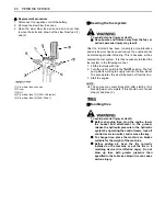
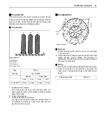
Page 108: ...upply fuel into the line About 10 seconds later the air will be bled out from the line 3 Start the engine A The engine may sometimes stall after starting if air bleeding was not complete If this should occur repeat step 2 and step 3 TIRES BHandling tires To avoid personal injury or death A Before changing tires stop the engine lower the bucket and attachment to the ground release the hydraulic pre...

Page 109: ...ive force of the machine to decrease or the tire to slip There is also the risk of a blow out BChanging tires C Removal 1 Loosen the wheel nuts each by one turn on the wheel to be removed 2 Lift the machine so that the wheel to be removed is just raised off the ground Place the machine on jackstands Then remove the wheel nuts and remove the wheel from the axle C Fitting 1 Mount wheel on axle and l...

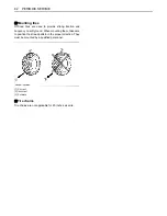
Page 110: ...trong traction and buoyancy on soft ground When mounting them take care to position their tread pattern in the proper direction They must be mounted by a qualified personnel BTire chains Tire chains are not applicable for 20 inches size tire 1 Correct 2 Incorrect 3 Forward ...

Page 111: ... the piston rods of the hydraulic cylinders where they are exposed 4 Remove and store the battery separately 5 Check the anti freeze in the coolant Add anti freeze for adequate protection down to 25 C Measures during storing 1 Recharge the battery regularly C Restarting after storing 1 Remove the grease applied to the piston rods of the hydraulic cylinders 2 Check all oil levels the sediment trap ...

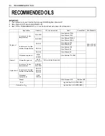
Page 112: ...C MIL L 2104D SAE 20W Shell Rotella T20W 2 Shell Rimula 20W 2 In summer or by high ambient temperatures SAE 30 Shell Rotella T30 Shell Rimula 30 SAE 40 Shell Rotella T40 Shell Rimula 40 SAE 50 Shell Rimula 50 All season engine oil Multi purpose Shell Rottela T15W 40 Gear oil All weather gear oil 80W API GL 4 TOTAL DYNATRANS FR Hydraulic oil In winter or by low temperatures SAE 5W SAE 10W In summer...

Page 113: ...harge or replace battery Insufficient engine power Low fuel level Check fuel and add if necessary Clogged air cleaner Clean the air cleaner element Engine suddenly stops Low fuel level Check fuel and add if necessary Purge the fuel system Abnormal exhaust gas color Poor fuel Use high quality fuel Too much engine oil Drain engine oil to prescribed oil level Water temperature in red zone Overheating...

Page 114: ...t Armrest is in Raised position Operator is not in the operator s seat Hydraulic unlock lever is not pressed Lower the armrests Sit in the operator s seat Press the hydraulic unlock switch Electric system mark appears in the instrument panel Electric system is malfunction Check the error code number of next page and contact your local dealer Trouble Cause Countermeasure ...

Page 115: ...setting by the speed control switch Immediately contact your local dealer E 024 Differential lock Differential lock does not work Immediately contact your local dealer E 025 Parking brake Parking brake is not active The machine would be in neutral Immediately contact your local dealer E 026 Solenoid for traveling forward Solenoid for traveling forward is not active and the machine would be in neut...

Page 116: ...rning For correction refer to the Coolant Temperature Gauge section page 18 If this error code number still appears immediately contact your local dealer E 9118 Engine oil pressure system Stop the engine and check the engine oil level If this error code number still appears immediately contact your local dealer E 9119 Charging system failure Stop the engine and check the V belt If this error code ...

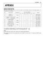
Page 117: ...he service hour meter replaced due to any trouble with it the meter is set to 0 Contact your KUBOTA dealer for details No Check points Measures Hour meter indicator Intervals 50 100 250 500 600 750 1000 1 Engine oil change every 250 hrs 2 Hydraulic oil every 1000 hrs 3 Air cleaner element Outer element replace every 1000 hrs Inner element every 1000 hrs 4 Fuel filter cartridge replace every 500 hr...

Reviews: