6-S20
MX5100, WSM
FRONT AXLE
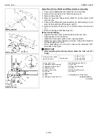
Clearance between Front Axle Case Bosses and Bracket
Bushings
1. Measure the front axle case bosses O.D. with an outside
micrometer.
2. Measure the bracket bushing I.D. and calculate the clearance.
3. If the clearance exceeds the allowable limit, replace the bracket
bushing.
■
Press-fitting Bushing
• When press-fitting a new bushing, observe the dimension
described in the figure.
NOTE
■
• After replacing the bushing, be sure to adjust the front axle
rocking force. (See page 6-S7.)
W10194290
Clearance between Bevel Gear Case Boss and Front Axle
Support Bushing
1. Measure the bevel gear case boss O.D. with an outside
micrometer.
2. Measure the support bushing I.D. and calculate the clearance.
3. If the clearance exceeds the allowable limit, replace it.
W10198060
Clearance between front
axle case boss (front)
and bracket bushing
(front)
Factory spec.
0.025 to 0.160 mm
0.00098 to 0.00630 in.
Allowable limit
0.35 mm
0.0138 in.
Front axle case boss
(front) O.D.
Factory spec.
49.950 to 49.975 mm
1.96653 to 1.96752 in.
Bracket bushing (front)
I.D.
Factory spec.
50.000 to 50.110 mm
1.96850 to 1.97283 in.
Clearance between front
axle case boss (rear)
and bracket bushing
(rear)
Factory spec.
0.025 to 0.190 mm
0.00098 to 0.00748 in.
Allowable limit
0.35 mm
0.0138 in.
Front axle case boss
(rear) O.D.
Factory spec.
70.000 to 70.035 mm
2.75590 to 2.75728 in.
Bracket bushing (rear)
I.D.
Factory spec.
70.060 to 70.190 mm
2.75826 to 2.76338 in.
Press-fit depth of
bushing (A)
Reference value
12.0 to 13.0 mm
0.47 to 0.51 in.
(1) Bushing
A : Depth of Bushing
Clearance between
bevel gear case boss
and front axle support
bushing
Factory spec.
0.060 to 0.220 mm
0.00236 to 0.00860 in.
Allowable limit
0.50 mm
0.0197 in.
Bevel gear case boss
O.D.
Factory spec.
54.970 to 55.000 mm
2.16417 to 2.16535 in.
Front axle support
bushing I.D.
Factory spec.
55.060 to 55.190 mm
2.16772 to 2.17283 in.
Summary of Contents for MX5100
Page 2: ......
Page 8: ...6 MX5100 WSM SAFETY INSTRUCTIONS...
Page 9: ...7 MX5100 WSM SAFETY INSTRUCTIONS...
Page 12: ...10 MX5100 WSM DIMENSIONS DIMENSIONS...
Page 13: ...11 MX5100 WSM DIMENSIONS...
Page 14: ...12 MX5100 WSM DIMENSIONS...
Page 15: ...G GENERAL...
Page 16: ......
Page 18: ......
Page 87: ...1 ENGINE...
Page 88: ......
Page 90: ......
Page 92: ......
Page 166: ...1 S74 MX5100 WSM ENGINE...
Page 167: ...2 CLUTCH...
Page 168: ......
Page 170: ......
Page 174: ...2 M4 MX5100 WSM CLUTCH...
Page 176: ......
Page 205: ...3 TRANSMISSION...
Page 206: ......
Page 208: ......
Page 209: ...3 M1 MX5100 WSM TRANSMISSION 1 STRUCTURE 1 2WD...
Page 210: ...3 M2 MX5100 WSM TRANSMISSION 2 4WD...
Page 218: ......
Page 265: ...4 REAR AXLE...
Page 266: ......
Page 267: ...CONTENTS MECHANISM 1 STRUCTURE 4 M1...
Page 268: ......
Page 270: ...4 M2 MX5100 WSM REAR AXLE...
Page 272: ......
Page 278: ...4 S6 MX5100 WSM REAR AXLE...
Page 279: ...5 BRAKES...
Page 280: ......
Page 281: ...CONTENTS MECHANISM 1 STRUCTURE 5 M1...
Page 282: ......
Page 286: ......
Page 296: ...5 S10 MX5100 WSM BRAKES...
Page 297: ...6 FRONT AXLE...
Page 298: ......
Page 300: ......
Page 306: ......
Page 327: ...7 STEERING...
Page 328: ......
Page 330: ......
Page 334: ...7 M4 MX5100 WSM STEERING...
Page 336: ......
Page 355: ...8 HYDRAULIC SYSTEM...
Page 356: ......
Page 358: ......
Page 374: ......
Page 402: ...8 S28 MX5100 WSM HYDRAULIC SYSTEM...
Page 403: ...9 ELECTRICAL SYSTEM...
Page 404: ......
Page 406: ......
Page 407: ...9 M1 MX5100 WSM ELECTRICAL SYSTEM 1 WIRING DIAGRAM...
Page 420: ......
Page 454: ...9 S34 MX5100 WSM ELECTRICAL SYSTEM...


