


TRANSAXLE
GR1600EU, WSM
2-S36
(Continued)
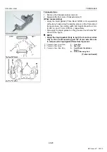
1. Align the bolt holes of PTO cover assembly (13) with the stud
bolts (1). Then slide the PTO cover assembly (13) slowly in
direction of arrow in figure.
2. When the distance
"A"
is 15 to 16 mm (0.59 to 0.62 in.), the
PTO cover assembly (13) would be blocked from sliding.
In this case, push the PTO cover assembly (13) softly while
slightly turning the PTO shaft (12).
3. When the distance
"A"
is 8.0 to 9.0 mm (0.32 to 0.35 in.), the
PTO cover assembly (13) may be blocked from sliding again
because the tongues (16) of brake friction plate do not align with
the grooves (14) of transaxle case.
In this case, slightly pull out the PTO shaft (12), and turn the
brake friction plate 2 with a minus screwdriver so that the
tongues (16) of it align with the grooves (14) of transaxle case.
NOTE
• Do not touch the liquid gasket applied on the PTO cover
assembly (13).
4. When the tongues (16) of brake friction plate 2 align with the
grooves of transaxle case, further push the PTO cover
assembly (13). If the PTO cover assembly (13) is installed
correctly, the distance
"A"
should become 5.0 mm (0.20 in.) or
less.
5. Install the PTO cover mounting bolts in three remained bolt
holes. And tighten them slowly and evenly until the PTO cover
assembly (13) contacts to the transaxle case.
6. Remove the stud bolts (1), and replace with the PTO cover
mounting bolts. Then tighten all bolts with the specific torque.
7. Check the following movement of PTO shaft (12) while raising
the PTO arm (18).
(To be continued)
Position of PTO Arm (18)
Movement of PTO Shaft (12)
1
Within a play from the lowest
position
Can Not be turned by hand
2
Range where clutch spring
resistance is felt
Can be turned by hand
3
PTO arm is the highest position
Can Not be turned by hand
Tightening torque
PTO Cover Mounting Bolt
18 to 20 N·m
1.8 to 2.1 kgf·m
13 to 15 lbf·ft
(1) Stud bolt
(12) PTO Shaft
(13) PTO Cover Assembly
(14) Groove
(15) Transaxle Case
(16) Tongue
(17) PTO Cover Mounting Bolt
(18) PTO Arm
KiSC issued 11, 2013 A
Summary of Contents for GR1600EU
Page 1: ...GR1600EU WORKSHOP MANUAL KiSC issued 11 2013 A ...
Page 4: ...I INFORMATION KiSC issued 11 2013 A ...
Page 10: ...INFORMATION GR1600EU WSM I 5 9Y1210595INI0002US0 KiSC issued 11 2013 A ...
Page 11: ...INFORMATION GR1600EU WSM I 6 9Y1210595INI0003US0 KiSC issued 11 2013 A ...
Page 12: ...INFORMATION GR1600EU WSM I 7 9Y1210595INI0007US0 KiSC issued 11 2013 A ...
Page 16: ...INFORMATION GR1600EU WSM I 11 2 GR1600ID 9Y1210595INI0009US0 KiSC issued 11 2013 A ...
Page 17: ...G GENERAL KiSC issued 11 2013 A ...
Page 80: ...1 ENGINE KiSC issued 11 2013 A ...
Page 138: ...2 TRANSAXLE KiSC issued 11 2013 A ...
Page 194: ...3 BRAKES KiSC issued 11 2013 A ...
Page 195: ...CONTENTS 1 BRAKE MECHANISM 3 M1 MECHANISM KiSC issued 11 2013 A ...
Page 205: ...4 FRONT AXLE KiSC issued 11 2013 A ...
Page 213: ...5 STEERING KiSC issued 11 2013 A ...
Page 221: ...6 ELECTRICAL SYSTEM KiSC issued 11 2013 A ...
Page 223: ...ELECTRICAL SYSTEM GR1600EU WSM 6 M1 1 WIRING DIAGRAM 1 GR1600EU GR1600F KiSC issued 11 2013 A ...
Page 224: ...ELECTRICAL SYSTEM GR1600EU WSM 6 M2 2 GR1600ID KiSC issued 11 2013 A ...
Page 257: ...7 MOWER KiSC issued 11 2013 A ...