background image


ROTEX

®


Operating/Assembly instructions 

KTR-N 
Sheet: 
Edition: 

40210 EN 
8 of 22 
22 


Please observe protection 

note ISO 16016. 

Drawn: 

2017-09-06 Pz/Bru 

Replacing: 

KTR-N dated 2017-01-02 

Verified: 

2017-09-06 Pz 

Replaced by: 


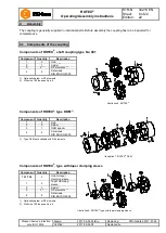
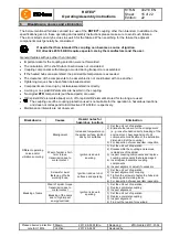
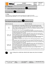
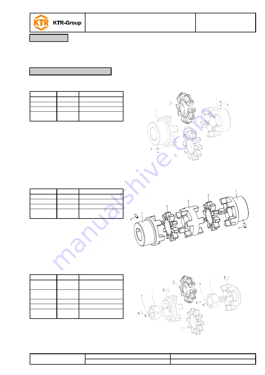
The coupling is generally supplied in individual parts. Before assembly the coupling has to be inspected for 
completeness. 


Components of ROTEX

®

, shaft coupling type No. 001


Component 

Quantity 

Description 


Illustration 6: ROTEX

®


Hub 

Spider 

1)


2)


DZ elements 

1)


Setscrews 
DIN EN ISO 4029 

1)  Optionally spider or DZ elements 
2)  With size 180 the quantity is 6. 


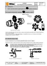
Components of ROTEX

®

, type DKM 

1)


Component 

Quantity 

Description 


Illustration 7: ROTEX

®

 DKM 

Hub 

Spider 

DKM spacer 

Setscrews 
DIN EN ISO 4029 

1)  Type DKM not available with DZ elements. 


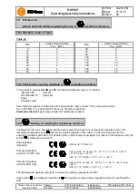
Components of ROTEX

®

, type with taper clamping sleeve


Component 

Quantity 

Description 


Illustration 8: ROTEX

®

 type with taper clamping sleeve 

TB1/TB2 

Hub for taper 
clamping sleeve 

Taper clamping 
sleeve 

Spider 

1)


2)


DZ elements 

1)


Setscrews 
DIN EN ISO 4029 

1)  Optionally spider or DZ elements 
2)  With size 180 the quantity is 6. 


Assembly 

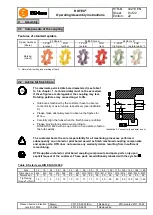
4.1  Components of the coupling 

Summary of Contents for ROTEX 001

Page 1: ...ted 2017 01 02 Verified 2017 09 06 Pz Replaced by ROTEX Torsionally flexible jaw type couplings No 001 shaft coupling No 018 DKM with taper clamping sleeve and their combinations according to directive 2014 34 EU for finish bored pilot bored and unbored couplings Type No 001 shaft coupling Type No 018 DKM double cardanic coupling Type with taper clamping sleeve ...

Page 2: ...ansport and packaging 7 3 1 Storage 7 3 2 Transport and packaging 7 4 Assembly 8 4 1 Components of the coupling 8 4 2 Advice for finish bore 9 4 3 Assembly of the hubs 10 4 4 Assembly of taper clamping sleeve 11 4 5 Displacements alignment of the couplings 12 5 Start up 14 6 Breakdowns causes and elimination 15 7 Disposal 17 8 Maintenance and service 17 9 Spares inventory customer service addresse...
Page 3: ... 560 14 45 126 50 26 20 3 0 95 46 75 40 1a 42 55 94 1b 14 55 176 75 65 48 1 310 525 655 15 52 140 56 28 21 3 5 105 51 85 45 1a 48 62 104 1b 15 62 188 80 69 55 1 410 685 825 20 60 160 65 30 22 4 0 120 60 98 52 1a 55 74 118 65 1 625 940 1175 22 70 185 75 35 26 4 5 135 68 115 61 75 1 1280 1920 2400 30 80 210 85 40 30 5 0 160 80 135 69 90 1 2400 3600 4500 40 97 245 100 45 34 5 5 200 218 230 100 160 81...

Page 4: ...5 26 4 5 135 68 115 47 1b 235 100 135 75 1 1280 1920 2400 0 95 210 85 40 30 5 0 160 80 135 53 1b 260 110 160 90 1 2400 3600 4500 0 110 245 100 45 34 5 5 200 218 230 100 160 62 1b 295 125 200 Table 4 Type DKM 5 Size Spider 1 component 2 Rated torque Nm Dimensions mm 3 Dimensions d D D1 General 92 ShA 98 ShA LDKM l1 l2 E b s DH dH l11 l12 19 10 17 see table 1 to 3 92 25 16 12 2 0 40 18 10 42 24 35 6...

Page 5: ...75 3020 3 90 1 2400 3600 25 75 149 52 45 34 5 5 200 218 230 100 160 14 3020 100 1 3300 4950 35 90 230 90 50 38 6 0 225 246 260 113 180 69 3535 125 1 6650 10000 55 110 288 114 60 46 7 0 290 315 330 147 230 86 4545 1 Maximum torque of the coupling TKmax rated torque of the coupling TK rated x 2 2 DZ1 internal diameter of housing 3 Available for type TB2 only ROTEX couplings with attachments that can...

Page 6: ...g parts Please make absolutely sure to read through and observe the following safety indications All operations on and with the coupling have to be performed taking into account safety first Please make sure to switch off the power pack before you perform your work on the coupling Secure the power pack against accidental switch on e g by providing warning signs at the place of switch on or removin...

Page 7: ...he couplings supplied by KTR should be considered as components not machines or partly completed machines according to EC Machinery Directive 2006 42 EC Consequently KTR does not have to issue a declaration of incorporation For details about safe assembly start up and safe operation please refer to the present operating assembly instructions considering the warnings The coupling hubs are supplied ...

Page 8: ... 1 4 2 Setscrews DIN EN ISO 4029 1 Optionally spider or DZ elements 2 With size 180 the quantity is 6 Components of ROTEX type DKM 1 Component Quantity Description Illustration 7 ROTEX DKM 1 2 Hub 2 2 Spider 3 1 DKM spacer 4 2 Setscrews DIN EN ISO 4029 1 Type DKM not available with DZ elements Components of ROTEX type with taper clamping sleeve Component Quantity Description Illustration 8 ROTEX t...

Page 9: ...refully align the hubs when the finish bores are drilled Please provide for a setscrew according to DIN EN ISO 4029 with a cup point or an end plate to fasten the hubs axially Illustration 9 Concentricity and axial runout The customer bears the sole responsibility for all machining processes performed subsequently on unbored or pilot bored as well as finish machined coupling components and spare p...

Page 10: ...the shaft Please pay attention to the ignition risk in hazardous locations STOP Touching the heated hubs causes burns Please wear safety gloves With the assembly please make sure that the distance dimension E see table 1 to 5 is observed to allow for axial clearance of the spider when in operation Disregarding this advice may cause damage to the coupling Mount the hubs on the shaft of driving and ...

Page 11: ...process of screwing the hub is mounted onto the taper sleeve and thus the sleeve is pressed onto the shaft By light blows of the hammer the taper clamping sleeve must be pushed further into the taper bore by means of a suitable sleeve Afterwards please re tighten the setscrews at the tightening torque indicated in table 8 This process must be performed at least once After the drive has operated un...

Page 12: ...ple heat expansion or foundation settling In order to ensure a long service life of the coupling and avoid dangers with the use in hazardous locations the shaft ends must be accurately aligned Please absolutely observe the displacement figures indicated see table 9 to 11 If the figures are exceeded the coupling will be damaged The more accurate the alignment of the coupling the longer is its servi...

Page 13: ... 00 2 30 2 90 3 80 4 20 5 00 Table 10 Displacement figures for 64 Shore D Size 14 19 24 28 38 42 48 55 65 75 90 100 110 125 140 160 180 Max axial displacement Ka mm 0 5 0 5 0 5 0 7 0 7 1 0 1 0 1 0 1 0 1 5 1 5 1 5 2 0 2 0 2 0 2 5 3 0 1 0 1 2 1 4 1 5 1 8 2 0 2 1 2 2 2 6 3 0 3 4 3 8 4 2 4 6 5 0 5 7 6 4 Max radial displacement Kr mm with 1500 rpm 0 11 0 13 0 15 0 18 0 21 0 23 0 25 0 27 0 30 0 34 0 36 ...

Page 14: ...r covers with unlocked openings on the top face no light metals must be used if the couplings are used as equipment of equipment group ll if possible from stainless steel If the couplings are used in mining equipment group l M2 the cover must not be made of light metal In addition it must be resistant to higher mechanical loads than if it is used as equipment of equipment group ll The minimum dist...

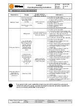
Page 15: ...tection used is not suitable for the operation in hazardous locations and does not correspond to EU directive 2014 34 EU respectively Maintenance intervals are not observed Breakdowns Causes Hazard notes for hazardous locations Elimination Different operating noise and or vibrations occuring Misalignment Increased temperature on the spider surface ignition risk by hot surfaces 1 Set the unit out o...

Page 16: ... unit out of operation 2 Disassemble the coupling and remove remainders of the spider 3 Inspect coupling components and replace coupling components that are damaged 4 Insert spider assemble coupling components 5 Inspect alignment adjust if necessary 6 Make sure that further physical modifications of the spider are excluded Ambient contact temperatures which are too high for the spider max permissi...

Page 17: ... machine bearings of the driving and driven side settle during the course of load please inspect the alignment of the coupling and re align the coupling if necessary The coupling parts have to be inspected for damages The screw connections have to be inspected visually Having started up the coupling the tightening torques of the screws have to be inspected during the usual inspection intervals Wit...

Page 18: ...dia class G gases fogs steams zone 1 and 2 coupling is not approved for zone 0 Media class D dusts zone 21 and 22 coupling is not approved for zone 20 Explosion group IIC explosion class IIA and IIB are included in IIC Temperature class T PUR PUR Temperature class Ambient or operating temperature Ta Max surface temperature Temperature class Ambient or operating temperature Ta Max surface temperatu...

Page 19: ...at the latest after 18 months provided that the operating parameters remain the same If you note significant wear during the initial inspection so that it would be recommendable to replace the spider DZ elements please find out the cause according to the table Breakdowns if possible The maintenance intervals must be adjusted to the modified operating parameters without fail II 2GD c IIC T4 T5 T6 A...

Page 20: ...espective of the inspection intervals In case of backlash X mm the flexible spider DZ elements must be replaced Reaching the limits for replacing depends on the operating conditions and the existing operating parameters In order to ensure a long service life of the coupling and avoid dangers with the use in hazardous locations the shaft ends must be accurately aligned Please absolutely observe the...

Page 21: ...at least one component completely and on the remaining components by an label on the outside diameter of the hub or on the front side each for the operating conditions permitted The flexible spider or DZ element is excluded For reason of limited space only the symbol is stamped up to size 19 Short labelling standard II 2GD c IIC T X I M2 c X Complete labelling valid for T PUR only II 2G c IIC T6 T...

Page 22: ...s with the specifications of the following standards guidelines DIN EN 1127 1 DIN EN 1127 2 DIN EN 13463 1 DIN EN 13463 5 CLC TR 50404 The ROTEX is in accordance with the specifications of the directive 2014 34 EU One or several directives mentioned in the corresponding type examination certificate IBExU13ATEXB016 X were in part replaced by updated versions KTR Systems GmbH being the manufacturer ...

Reviews: