ROTEX
®
Operating/Assembly instructions
KTR-N
Sheet:
Edition:
40210 EN
21 of 22
22
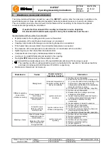
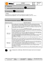
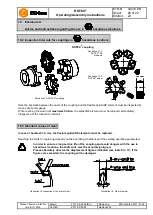
Please observe protection
note ISO 16016.
Drawn:
2017-09-06 Pz/Bru
Replacing:
KTR-N dated 2017-01-02
Verified:
2017-09-06 Pz
Replaced by:
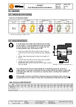
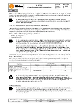
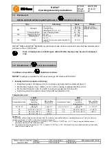
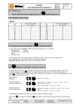
Table 12:
Size
Limits of wear (friction)
Size
Limits of wear (friction)
X
max.
[mm]
X
max.
[mm]
9
2
65
5
14
2
75
6
19
3
90
8
24
3
100
9
28
3
110
9
38
3
125
10
42
4
140
12
48
4
160
14
55
5
180
14
In the explosion groups
IIA
,
IIB
and
IIC
the following materials may be combined:
EN-GJL-250
(GG 25)
EN-GJS-400-15
(GGG 40)
Steel
Stainless steel
Semi-finished products of aluminium with a magnesium share of up to 7.5°% and a yield point of
R
p0.2
≥ 250 N/mm
2
are permitted for the use in hazardous locations.
Aluminium diecast
is generally excluded for hazardous locations.
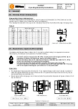
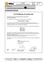
Couplings for the use in hazardous locations are marked on at least one component completely and on the
remaining components by an
label on the outside diameter of the hub or on the front side each for the
operating conditions permitted. The flexible spider or DZ element is excluded. For reason of limited space only the
symbol
is stamped up to size 19.
Short labelling:
(standard)
II 2GD c IIC T X/I M2 c X
Complete labelling:
(valid for T-PUR
®
only)
II 2G c IIC T6, T5, T4 resp. T3 - 50 °C
T
a
+ 65 °C, + 80 °C,
+ 115 °C resp. + 120 °C
II 2D c T 140 °C/I M2 c - 50 °C
T
a
+ 120 °C
Complete labelling:
(valid for PUR only)
II 2G c IIC T6, T5 resp. T4 - 30 °C
T
a
+ 65 °C, + 80 °C resp.
+ 90 °C
II 2D c T 110 °C/I M2 c - 30 °C
T
a
+ 90 °C
The labelling with explosion group llC includes the explosion groups llA and llB.
If the symbol
was stamped in addition to
, the coupling component was supplied unbored or pilot bored by
KTR.
10
Enclosure A
Advice and instructions regarding the use in
hazardous locations
10.3 Standard values of wear
10.4 Permissible coupling materials in
hazardous locations
10.5
marking of coupling for hazardous locations

