ROTEX
®
SP "Non Sparking"
Operating/Assembly instructions
KTR-N
Sheet:
Edition:
40228 EN
3 of 28
6
Please observe protection
note ISO 16016.
Drawn:
2019-10-10 Pz/Bru
Replacing:
KTR-N dated 2017-01-02
Verified:
2019-10-10 Pz
Replaced by:
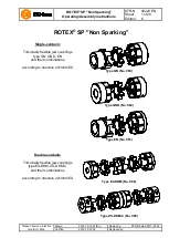
Illustration 1: Type GN (No. 080) - component 1, 1a, 1b: steel (St)
Illustration 2: Type GN (No. 080) - component 1, 1a, 1b: cast iron (GJL)
Table 1: Type GN (No. 080) - component 1, 1a, 1b: steel (St)
Size
Spider
1)
(component
2)
Rated torque
[Nm]
Com-
po-
nent
(St)
Dimensions [mm]
3)
Component 1, 1a, 1b steel (St)
Com-
po-
nent
Dimensions [mm]
3)
Component 1c
Max.
finish
bore d
1
2)
L
l
1
E
b
s
D
H
d
H
D, D
1
N
Max.
finish
bore d
2
2)
l
2
D
A
24
35
1a
35
78
30
18
14
2.0
55
27
55
-
1c
28
30
61
1b
98
50
28
95
1a
40
90
35
20
15
2.5
65
30
65
-
1c
32
35
72
1b
115
60
38
190
1
48
114
45
24
18
3.0
80
38
70
27
1c
42
45
87
1b
139
70
80
-
42
265
1
55
126
50
26
20
3.0
95
46
85
28
1c
48
50
103
1b
151
75
995
-
48
310
1
62
140
56
28
21
3.5
105
51
95
32
1c
55
56
114
1b
164
80
105
-
55
410
1
74
160
65
30
22
4.0
120
60
110
37
1c
65
65
130
1b
185
90
120
-
65
625
1
80
185
75
35
26
4.5
135
68
115
47
1c
75
75
146
1b
210
100
135
-
Table 2: Type GN (No. 080) - component 1, 1a, 1b: cast iron (GJL)
Size
Spider
1)
(component
2)
Rated torque
[Nm]
Com-
po-
nent
(GJL)
Dimensions [mm]
3)
Component 1, 1a, 1b: cast iron (GJL)
Com-
po-
nent
Dimensions [mm]
3)
Component 1c
Max.
finish
bore d
1
2)
L
l
1
E
b
s
D
H
d
H
D, D
1
N
Max.
finish
bore d
2
2)
l
2
D
A
38
190
1
40
114
45
24
18
3.0
80
38
66
37
1c
42
45
87
1a
48
78
1b
139
70
62
42
265
1
45
126
50
26
20
3.0
95
46
75
40
1c
48
50
103
1a
55
94
1b
151
75
65
48
310
1
52
140
56
28
21
3.5
105
51
85
45
1c
55
56
114
1a
62
104
1b
164
80
69
55
410
1
60
160
65
30
22
4.0
120
60
98
52
1c
65
65
130
1a
74
118
65
625
1
70
185
75
35
26
4.5
135
68
115
61
1c
75
75
146
1) Maximum torque of the coupling T
Kmax.
= rated torque of the coupling T
K rated
x 2
2) Bores H7 with keyway to DIN 6885 sheet 1 [JS9] and setscrew
3) Dimensions G and t see table 9.
1
Technical data


