background image

-14-

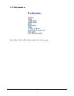
3.2 Configuration

Each of them will be described in detail orderly in the following sections.

Summary of Contents for KGS-1602

Page 1: ... 1 DOC 050724 KGS 2402 Web Samrt 24 Port Gigabit Ethernet Switch with SFP support Installation Guide ...

Page 2: ...rves the right to revise this documentation and to make changes in content from time to time without obligation on the part of KTI Networks Inc to provide notification of such revision or change For more information contact United States KTI Networks Inc P O BOX 631008 Houston Texas 77263 1008 Phone 713 2663891 Fax 713 2663893 E mail kti ktinet com URL http www ktinet com International Fax 886 2 2...

Page 3: ...nterface cables and AC power cord if any must be used in order to comply with the emission limits CISPR A COMPLIANCE This device complies with EMC directive of the European Community and meets or exceeds the following technical standard EN 55022 Limits and Methods of Measurement of Radio Interference Characteristics of Information Technology Equipment This device complies with CISPR Class A WARNIN...

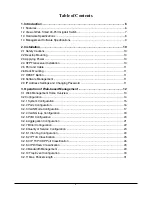
Page 4: ...anging Password 11 3 Operation of Web based Management 12 3 1 Web Management Home Overview 13 3 2 Configuration 14 3 2 1 System Configuration 15 3 2 2 Ports Configuration 16 3 2 3 VLAN Mode Configuration 17 3 2 4 VLAN Group Configuration 18 3 2 5 PVID Configuration 20 3 2 6 Aggregation Configuration 21 3 2 7 Mirror Configuration 22 3 2 8 Quality of Service Configuration 23 3 2 8 1 Vlan Tag Configu...

Page 5: ... 5 3 3 Monitoring 32 3 3 1 Statistics Overview 32 3 3 2 Detailed Statistics 33 3 4 Maintenance 35 3 4 1 Status 35 3 4 2 Warm Restart 37 3 4 3 Factory Default 38 3 4 4 Software Update 39 3 4 5 Logout 40 ...

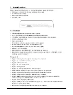
Page 6: ...ont panel diagnostic LEDs System Power Copper Port1 24 LINK ACT 10 100 1000Mbps and SFP LINK ACT Management Supports concisely the status of port and easily port configuration Supports per port traffic monitoring counters Supports port mirror function Supports the static trunk function Supports 802 1Q VLAN Supports user management and limits one user to login Maximal packet length can be up to 921...

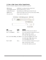
Page 7: ...e switch to factory defaults AC power socket Power socket for AC power cord LED Color Function System POWER Green ON when 5V DC power is on and good Port 1 to 24 LINK ACT Green ON when connection with remote device is good Blink when any traffic is present Off when cable connection is not good Port 1 to 24 10 100 1000Mbps Green Ember ON green when 1000Mbps speed is active ON ember when 100Mbps spe...

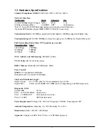
Page 8: ...g Rate Speed 1 488 000pps 1000Mbps 148 800pps 100Mbps 14 880pps 10Mbps MAC Address and Self learning 8K MAC address VLAN Table 4K VLAN table entries Buffer Memory Embedded 400 KB frame buffer Flow Control IEEE802 3x compliant for full duplex Backpressure flow control for half duplex Cable and Maximum Length Gigabit copper Cat 5 UTP cable Cat 5e recommended up to 100m Gigabit fiber 50 125 60 125 MM...

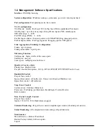
Page 9: ...fer mode Ingress traffic of the source ports Sniffer port one port Source ports multiple ports are allowed Quality of Service QoS Priority class High and low Per port classification options 802 1p IP ToS IP DSCP IP TCP UDP Port L4 base Bandwidth Control Per port basis control Ingress Rate control All traffic rate Unicast rate Broadcast Multicast rate Egress Rate control All traffic rate Trap Event...

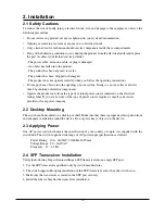
Page 10: ...ents Operate the product only from the type of external power source indicated on the electrical ratings label If you are not sure of the type of power source required consult your service provider or local power company 2 2 Desktop Mounting The switch can be mounted on a desktop or shelf Make sure that there is proper heat dissipation from and adequate ventilation around the device Do not place h...

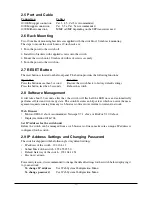
Page 11: ...Software Management It will take about 30 seconds after that the switch will flash all the LED once and automatically performs self test and is in ready state The switch features an http server which can serve the man agement requests coming from any web browser software over internet or intranet network Web Browser Microsoft IE 6 0 above recommended Netscape V7 1 above or FireFox V1 00 above Disp...

Page 12: ... admin Login For the first time to use please enter the default password then click the Apply button The login process now is completed In the switch it supports a simple user management function allowing only one administrator to config ure the system at the same time To optimize the display effect it is recommended to use Microsoft IE 6 0 above Netscape V7 1 above or FireFox V1 00 above Display ...

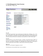
Page 13: ...serted The same if disconnected the port will show just dark if linked green Left side The main menu tree for web is listed in the page According to the function name in boldface all functions can be divided into three parts including Configuration Monitoring and Maintenance The functions of each folder are described in its corresponded section respectively As to the function names in normal type ...

Page 14: ... 14 3 2 Configuration Each of them will be described in detail orderly in the following sections ...

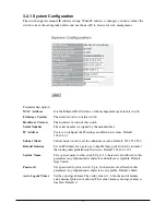
Page 15: ...es Default 192 168 1 1 Subnet Mask Subnet mask is used to set the subnet mask value Default 255 255 255 0 Default Gateway Set an IP address for a gateway to handle those packets that do not meet the routing rules predefined in the device Default 192 168 1 254 System Name Set a special name for this switch Up to 16 characters are allowed in this parameter Any alphanumeric character and null are acc...

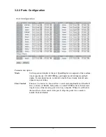
Page 16: ...eed mode no default value In Forced mode default value depends on your setting Flow Control There are two modes to choose in flow control including Enable and Disable If flow control is set Enable both parties can send PAUSE frame to the transmit ting device s if the receiving port is too busy to handle When it is set Disable there will be no flow control in the port It drops the packet if too muc...

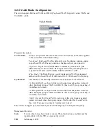
Page 17: ...ate 22 or 23 Port based VLAN groups Up link Port This function is enabled only when metro mode is chosen in VLAN mode 23 Except Port 23 each port of the switch cannot transmit packets with each other Each port groups a VLAN with Port 23 thus total 23 groups consisting of 2 members are formed 24 Except Port 24 each port of the switch cannot transmit packets with each other Each port groups a VLAN w...

Page 18: ...ased VLAN Group Setting or Port based VLAN Group Setting page which depends on your VLAN mode selection Description The description defined by administrator is associated with a VLAN group VID VLAN identifier Each tag based VLAN group has a unique VID It appears only in tag based mode Member This is used to enable or disable if a port is a member of the new added VLAN Enable means it is a member o...

Page 19: ... 19 Add a Tag based VLAN group Delete Group Just tick the check box t beside the ID then press the Delete Group button to delete the group Delete a Port based VLAN group Delete a Tag based VLAN group ...

Page 20: ...ged frame Note If Rule 1 is enabled and port 1 for example receives an untagged packet the switch will apply the PVID of port 1 to tag this packet the packet then will be for warded But if the PVID of port 1 is not 100 the packet will be dropped Tag This is an egress rule of the port Here you can choose untag or tag Tag means the outgoing packets must carry VLAN tag header just click the check box...

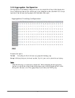
Page 21: ...e bandwidth of these ports Parameter description Normal Set up the ports that do not join any aggregation trunking group Group 1 8 Group the ports you choose together Up to 12 ports can be selected for each group Note Check the following to avoid errors in configuration When configuring the link aggregation function you should check that whether the aggregated ports are in full duplex mode as well...

Page 22: ...r the activation or deactivation of Port Mirror function the switch port mirror supported Ingress traffic only Default is disable Sniffer Port Set up the port for monitoring Valid port is Port 1 24 and default is Port 1 Source Port Set up the ports for being monitored Just tick the check box t under the port x and valid port is Port 1 24 Note When configuring the mirror function you should avoid s...

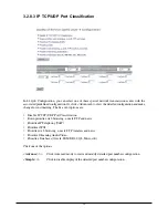
Page 23: ...TOS field is used to classify the priority class to which the packet belongs IP TCP UDP Port Classification In a received TCP or UDP packet the software Port number associated with the packet is checked and classified for the priority class Eight Port numbers can be configured This option also supports simple L4 configuration for some popular applications IP Deffserv Classification In a received I...

Page 24: ...n is allowed All select all ports 1 24 to simplify the procedure of configuration Class Each priority tag value is configured with a priority class High High Priority Low Low priority Note 1 Bit 0 Bit 1 Bit 2 represent the 3 bit value in priority tag field 2 Each port can be configured its own tag values and priority class mapping 3 Untagged packets are classified with Default Class ...

Page 25: ... ToS QoS Classification function work on them Multiple port selection is allowed All select all ports 1 24 to simplify the procedure of configuration Class Each ToS value is configured with a priority class High High Priority Low Low priority Note Bit 0 Bit 1 Bit 2 represent Bit 5 Bit 7 in TOS Field of IP Header in an IP packet ...

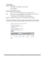
Page 26: ...event options are Disable IP TCP UDP Port Classification Down prioritize web browsing e mail FTP and news Prioritize IP Telephony VoIP Prioritize iSCSI Prioritize web browsing e mail FTP transfers and news Prioritize Streaming Audio Video Prioritize Databases Oracle IBM DB2 SQL Microsoft Click one of the options Advance Click Advanced mode to view and modify detailed port number configuration Simp...

Page 27: ...er can set up the port 1 24 respectively to let L4 QoS Classifi cation function work on them Multiple port selection is allowed All select all ports 1 24 to simplify the procedure of configuration Custom TCP UDP port number Up to 10 custom port numbers can be configured The following figure illustrates the predefined configuration when selecting option of Down prioritize web browsing e mail FTP an...

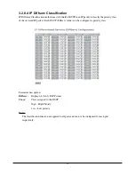
Page 28: ...ority class of the received IP packet Each DSCP Diffserv value can be configured a priority class Parameter description Diffserv Display 64 0 63 DSCP items Class Class assigned to the DSCP High High Priority Low Low priority Note The classification function are applied to all ports and can not be configured for each port respectively ...

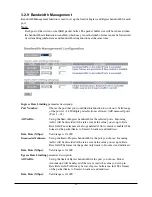
Page 29: ...oming traffic will be discarded if the rate exceeds the value you set up in Data Rate field Pause frames are also generated if flow control is enabled The format of the packet limits to Unicast broadcast and multicast Data Rate Mbps Valid range is 0 1000 Broadcast Multicasat Set up the limit of Ingress bandwidth for the port you choose Incoming traffic will be discarded if the rate exceeds the val...

Page 30: ...e the traps Two trap managers are supported System Events Warm Boot Warm Start Management operation event Cold Boot Power on event of the switch Illegal Login Invalid login event Port Events Link Up Port link up event Link Down Port link down event Rx error threshold Rx error over threshold event Tx error threshold Tx error over threshold event Error threshold The number of error packets in 5 seco...

Page 31: ...Length This function is used to limit the maximum packet length accepted by each port Jumbo Frame bytes Set up the maximum length of the packet that each port can accept Options 1518 1532 9216 bytes The default is 1532 bytes ...

Page 32: ... traffic of the port no matter the packet is good or bad If the counting is overflow the counter will be reset and restart counting Parameters description Tx Bytes Total transmitted bytes Tx Frames The counting number of the packet transmitted Rx Bytes Total received bytes Rx Frames The counting number of the packet received Tx Errors Number of bad packets transmitted Rx Errors Number of bad packe...

Page 33: ...ed broadcast packet Rx Multicast Show the counting number of the received multicast packet Tx Packets The counting number of the packet transmitted TX Octets Total transmitted bytes Tx High Priority Packets Number of Tx packets classified as high priority Tx Low Priority Packets Number of Tx packets classified as low priority Tx Broadcast Show the counting number of the transmitted broadcast packe...

Page 34: ...e frames in all packets transmitted Tx 512 1023 Bytes Number of 512 1023 byte frames in all packets transmitted Tx 1024 Bytes Number of 1024 max_length byte frames in all packets transmitted Rx CRC Alignment Number of Alignment errors and CRC error packets received Rx Undersize Number of short frames 64 Bytes with valid CRC Rx Oversize Number of long frames according to max_length register with va...

Page 35: ...e all settings back to factory default values Software Update Perform an update to the management firmware of the switch Logout Perform a logout from the switch 3 4 1 Status The status including System Status TP Port Status Fiber Port Status Aggregation VLAN Mirror Trap Event and Maximum Packet Length are contained in this function folder for port monitor and management ...

Page 36: ...er The number is 1 24 Both port 23 and 24 are optional modules Link Status Link Status will show the current active link speed and duplex Otherwise it shows Down Speed Display Auto or Forced the speed mode Flow Control Show each port flow control status Aggregation Normal Display the ports that do not join any aggregation trunking group Group 1 8 Display the members of the Group VLAN VLAN Mode Dis...

Page 37: ...Down Trap event enable setting and counter Rx error threshold Trap event enable setting and counter Tx error threshold Trap event enable setting and counter Error threshold Setting Maximum Packet Length Jumbo Frame bytes Display the settings about the maximum length of the packet that each port of the switch can accept Refresh Button to refresh all status 3 4 2 Warm Restart Warm Start function all...

Page 38: ...fault values except the IP address settings Note Function Current IP Address settings Other settings Factory Default web command No change Factory default values Push RESET button less 3 seconds No change No change Push RESET button for 3 seconds Factory default values Factory default values ...

Page 39: ...are updating procedures You must complete the updating procedure Note After pressing Yes if you encounter any problems or you want to quit the updating you must turn off the power to the switch for more than 5 seconds and turn it on to resume the manage ment operation Wait around 5 seconds and then click the Go button to enter software update page Click the Browse button to search for the file on ...

Page 40: ...ch also allows the user to logout manually by performing the Logout function If no action and no key is stroke as well in any function screen more than the minutes you set up in Auto Logout Timer the switch will have you logout automatically Or press the Logout button in Logout function to exit the system manually ...

Reviews: