-11-
2.5 Port and Cable
Connection
Cables
10/100M copper connection
Cat.3, 4, 5, Cat.5 is recommended
1000M copper connection
Cat. 5, 5e, Cat. 5e is recommended
1000M fiber connection
MMF or SMF depending on the SFP transceiver used
2.6 Rack Mounting
Two 19-inch rack mounting brackets are supplied with the switch for 19-inch rack mounting.
The steps to mount the switch onto a 19-inch rack are:
1. Turn the power to the switch off.
2. Install two brackets with supplied screws onto the switch.
2. Mount the switch onto 19-inch rack with rack screws securely.
3. Turn the power to the switch on.
2.7 RESET Button
The reset button is located on the front panel. The button provides the following functions:
Operation
Function
Press the button more than 3 second
Restore the switch back to factory default settings
Press the button less than 3 seconds
Reboot the switch
2.8 Software Management
It will take about 30 seconds, after that, the switch will flash all the LED once and automatically
performs self-test and is in ready state. The switch features an http server which can serve the man-
agement requests coming from any web browser software over internet or intranet network.
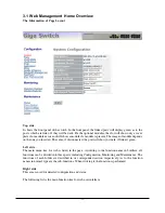
Web Browser
•
Microsoft IE 6.0 above recommended, Netscape V7.1 above or FireFox V1.00 above
•
Display resolution 1024x768.
Set IP Address for the switch unit
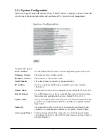
Before the switch can be managed from a web browser software, make sure a unique IP address is
configured for the switch.
2.9 IP Address Settings and Changing Password
The switch is shipped with the following factory default settings:
•
IP address of the switch : 192.168.1.1
•
Subnet Mask of the switch : 255.255.255.0
•
Default Gateway of the switch : 192.168.1.254
•
Password : admin
For security reason, it is recommended to change the default settings for the switch before deploying it
to your network:
To change IP address
Use Web System Configuration Menu
To change password
Use Web System Configuration Menu


