background image

Step 4: Turn on the UPS   

Press the ON button on the front panel for two seconds to power on the UPS.   

Note

: The battery charges fully during the first five hours of normal operation. Do not 

expect full battery run capability during this initial charge period.   

Step 5: Install software   

For optimal computer system protection, install UPS monitoring software to fully 
configure UPS shutdown. You may insert provided CD into CD-ROM to install the 
monitoring software. 

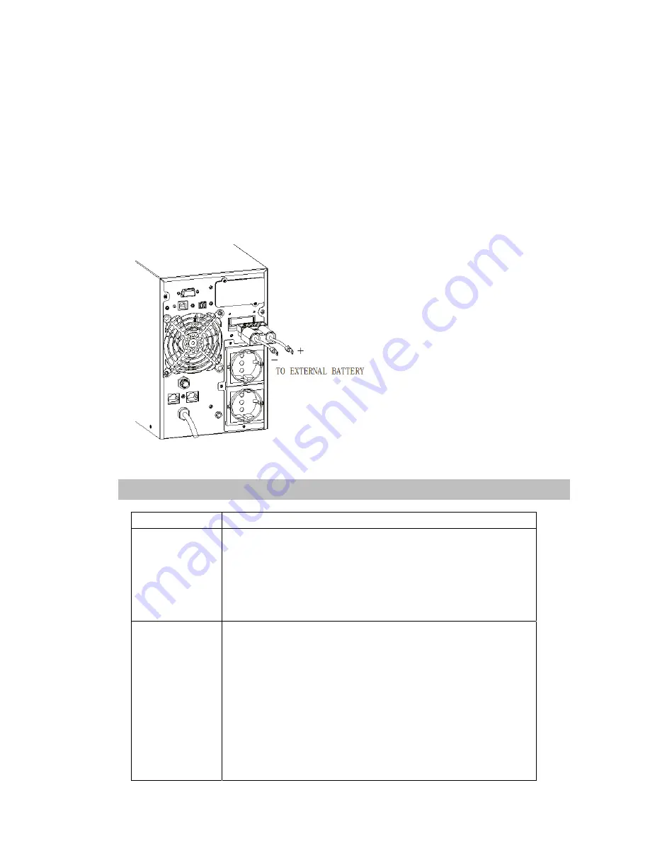
Step 6: External battery connection   

If your UPS is not including batteries. Please connect external batteries as below 
chart. 


3. Operations 

3-1 Button  operation 


Button Function 

ON Button 


Turn on the UPS

: Press and hold ON button for at least 

2 seconds to turn on the UPS. 


Down key

: Press this button to display next selection in 

UPS setting mode. 


Exit setting mode

:Press this button to confirm seletion 

and exit setting mode when LCD display the last 
selection in UPS setting mode. 

OFF Button 


Turn off the UPS

: Press and hold this button at least 2 

seconds to turn off the UPS in battery mode. UPS will 
be in standby mode under power normal or transfer to 
Bypass mode if the Bypass enable setting by pressing 
this button. 


Switch to bypass mode

: When the main power is 

normal, press and hold this button for 2 seconds. Then 
UPS will enter to bypass mode. This action will be 
ineffective when the input voltage is out of acceptable 
range. 


Up key

: Press this button to display previous selection 

in UPS setting mode. 

Summary of Contents for UDC9101RTH

Page 1: ...Uninterruptible Power Systems 1 2 3KVA Operation Manual 4256 1749 E...

Page 2: ...ut high frequency online UPS designed by our R D team who is with years of designing experiences on UPS With excellent electrical performance perfect intelligent monitoring and network functions smart...

Page 3: ...uide 3 2 Installation and setup 4 2 1 Unpack checking 4 2 2 Real panel view 4 2 3 LCD control panel 6 2 4 Setup the UPS 6 3 Operations 7 3 1 Button operation 7 3 2 LCD display 8 3 3 UPS setting 11 3 4...

Page 4: ...nt The UPS system must be absolutely dry before being installed Please allow at least two hours for the UPS system to acclimate the environment Do not install the UPS system near water or in moist env...

Page 5: ...voltage exists in the terminals of high capability capacitor such as BUS capacitors Only persons are adequately familiar with batteries and with the required precautionary measures may replace batter...

Page 6: ...use 2 1Unpack checking Don t lean the UPS when moving it out from the packaging Check the appearance to see if the UPS is damaged or not during the transportation do not switch on the UPS if any dama...

Page 7: ...C input 2 Network Fax Modem Surge Protection option 3 Input circuit breaker 4 EPO option 5 USB communication port option 6 RS 232 communication port 7 SNMP intelligent slot option 8 Output receptacles...

Page 8: ...k b Suggest using AWG14 or 2 1mm2 power cords for 3KVA 200 208 220 230 240VAC models c Upon completion of the wiring configuration please check whether the wires are securely affixed d Put the small c...

Page 9: ...on ON Button Turn on the UPS Press and hold ON button for at least 2 seconds to turn on the UPS Down key Press this button to display next selection in UPS setting mode Exit setting mode Press this bu...

Page 10: ...ds to disable or enable the alarm system But it s not applied to the situations when warnings or errors occur Switch to UPS self test mode Press and hold this button for 2 seconds to enter UPS self te...

Page 11: ...9 03 Output voltage 04 Load 05 Temperature EnvironmentTemperatu re 06 Firmware Version UPS model...

Page 12: ...ional status and mode 08 Alarm Code Warming Message All alarm codes are present when abnormal behavior s occur s 09 The charging status can also be shown on the screen as below while the charger is on...

Page 13: ...ages Item Settings Content Displayed 01 Mode setting Press Func button to change the setting ECO or NOR orCF Press UP button to select the previous setting Press DOWN button to select the next setting...

Page 14: ...on to select the previous setting Press DOWN button to select the next setting 06 Bypass voltage upper limit setting Press Func button to change the setting The bypass voltage upper limit range is 230...

Page 15: ...ble AC power to output The UPS will also charge the battery at online mode Inverter led light ECO mode Energy saving mode When the input voltage is within voltage regulation range UPS will bypass volt...

Page 16: ...t 18 Soft start failed Beep continuously Fault LED lit 19 UPS Inside Over Temperature Twice per second Fault LED lit 20 Heatsink Over Temperature Twice per second Fault LED lit 26 Battery over voltage...

Page 17: ...is overload Remove excess loads from UPS output Alarm code is shown as 29 and FAULT led light The UPS shut down automatically because short circuit occurs on the UPS output Check output wiring and if...

Page 18: ...n addition to the features of a standard NetAgent Mini NetAgent II has the option to add Net Feeler Lite to detect temperature humidity smoke andsecurity sensors Thus making NetAgent II aversatile man...

Page 19: ...ns definition of connecting terminal on the board Relaycard electrical parameter max Type Relaycardcontact Max Switched Voltage AC 120V DC 24V AC 120V DC 5 12V Max Switched Current AC 1A DC 1A AC 1A D...

Page 20: ...ltage point 230 264 setting the high voltage point in LCD from 230Vac to 264Vac Default 264Vac Bypass low voltage point 170 220 setting the low voltage point in LCD from 170Vac to 220Vac Default 170Va...

Page 21: ...fter 5 seconds when the utility is normal 130 UPS transfer to bypass immediately when the utility is normal Short Circuit Hold Whole System Overheat Line Mode Switch to Bypass Backup Mode Shut down UP...

Reviews: