background image

K.S.F.

6. SET UP

1.Take out the pin

2. A. Put down front legs

B. Put in the pin

C Take out the pin

.

A. Put down legs

B. Put in the pin

(MUST PUT IN B

3.

)

A

B

A

B

C

B

11

Summary of Contents for CA 400 GL

Page 1: ...CA 400 GL SAFETY MODEL CA 400 GL KeM Tech KSF UPTER design ...

Page 2: ......

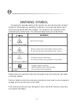
Page 3: ...achine for these warning symbols and ensure they are kept visible and clearly readable Failure to follow the instructions and safety precautions could result in serious equipment damage serious personal injury and or death If the warning symbols have been damaged or have come off the machine ensure they are replaced immediately WARNING Electric Shock Danger Danger of limbs and or clothing drawn in...

Page 4: ...st of this index This equipment can be operated correctly and safely only under the careful and right operation and maintenance Responsibility Statement In order to agree with the Hardware and Software explained in this manual we have verified the content of this manual carefully but it is not possible to understand all the differences Thus we cannot guarantee to meet with the standards for all of...

Page 5: ...um compact safety strength and reliability 2 Set Up without tools The LEGS can be release or fold out in seconds 3 Telescoping legs Versatile and infinitely adjustable available use in uneven ground for example stairway 4 Electric remote control with variable speed switch it can be used in soft start 5 Energency Stop Button press the button for stop raising or lowering 6 Automatic Overload Breaker...

Page 6: ...G SIZE 9 OPERATING SIZE OF 10 SIZE OF 11 PRE OPERATION INSPECTION 16 12 RAISING AND LOWERING 17 13 EMERGENCY STOP BUTTON MANUALLY 19 14 USE OF GLAZING INSTALLATION 15 25 17 18 EXPLODE VIEW OF CA 400 28 19 13 14 COUNTER WEIGHT SEAT 15 CRADLE 15 20 ORDINARY EXAMINATION 16 APPENDIX 26 EXPLODE VIEW OF MOTOR AND GEARBOX 27 EXPLODE VIEW OF CRADLE 29 ...

Page 7: ... FAILURE TO OBEY THE INSTRUCTIONS AND SAFETY RULES MAY RESULT IN DEATH SERIOUS INJURY AND PROPERTY DAMAGE Always keep the Portable Lifter away from the high voltage electrical wires 5 DO NOT move the Portable Lifter while it s in the raised position 6 DO NOT use the Portable Lifter on a moving surface or vehicle 7 DO NOT exceed Portable Lifter s load capacity 8 MAINTAIN a minimum 10 Use of incorre...

Page 8: ...e of tools not approved may damage the Portable Lifter and cause danger 19 PRESS the EMERGENCY STOP BUTTON and TURN OFF the power supply if problems occur during operation Stop using the machine immediately and contact an authorised repairer 3 1 DO NOT operate Portable Lifter in rain damp surroundings or on wet ground because of the risk of electric shock 2 DO NOT operate close to pertroleum produ...

Page 9: ...enter of Platform 8 Prior to use check the work area for drop offs holes bumps debris unstable or slippery surfaces or other possible hazardous conditions 1 DO NOT grab the electric cable or pull out it from a power point while the motor is operating This will avoid short circuiting the motor 2 Keep the electric cable away from sharp or hot object 3 If the electric cable is damaged please stop usi...

Page 10: ...ns or other possible hazards 1 The export delivery of the Portable Lifters are used the strong packing and put into the standard carton and then adopt the proper transportation way to deliver to the appointed place 2 Do not throwing the machine heavily or put the heavy objects on the machine while transport When piling up please go ahead according to the indicated piling numbers marked in carton 3...

Page 11: ...e metal rusting or any parts defected during transportation or storage we suggest the unit should only be stored for up to one year prior to use If it planned to be stored for longer than one year special treatments should be undertaken A strict machinery function test and quality control are undertaken prior to delivery of the Portable Lifter Upon receipt please check according to the following p...

Page 12: ...K S F 5 LEGEND CRADLE MOTOR AND GEARBOX TELESCOPING MAST FRONT LEG LEVEL ADJUSTABEL WHEEL 2 1 2 INCH WHEELS BRACE COUNTER AND SEAT WEIGHT 8 INCH WHEELS LEVEL FRONT LEG LEG LEG WHEEL ADJUSTABEL SCREW 10 ...

Page 13: ...K S F 6 SET UP 1 Take out the pin 2 A Put down front legs B Put in the pin C Take out the pin A Put down legs B Put in the pin MUST PUT IN B 3 A B A B C B 11 ...

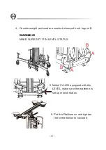
Page 14: ...ghten the screw below to secure it 4 Counter weight and seat are needed when put front legs in B MAKE SURE SET IT IN LEVEL STATUS WARNING B A B A 5 Model CA 400 equipped with the LEVEL make sure the machine is set up in level status 12 ...

Page 15: ...7 STORE DIMENSION K S F 13 960m m 550mm 650m m ...

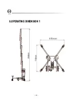
Page 16: ...8 OPERATING DIMENSION 1 K S F 14 970mm 3960 mm 1010 mm ...

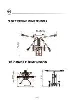
Page 17: ...10 CRADLE DIMENSION 9 OPERATING DIMENSION 2 K S F 15 1591mm 745m m 530 mm 1200 mm 1450mm ...

Page 18: ...BUT THE MAST CAN NOT BE RAISING JUST LIKE OPERATE IN MANUALLY IF EMERGENCY STOP BUTTON CAN NOT BE PULLED UP YOU MAY PRESS THE TRIGGER OF THE SWITCH BOX SLIGHTLY AS SOFT START WITH YOUR RIGHT HAND AND TWIST THE EMERGENCY STOP BUTTON A LITTLE BIT WITH YOUR LEFT HAND AS SHOWN THEN PULL IT UP YES RIGHT EMERGENCY STOP BUTTON IS COMPLETELY PULLED UP 2 Function Test 2 1 The function of Motor is normal or...

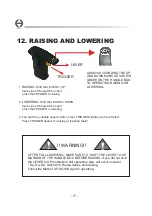
Page 19: ...ess TRIGGER deeper for raising or lowering faster LEVER ALWAYS ACCORDING THE UP AND DOWN MARK AS SHOWN ABOVE ON THE HANDLE BOX TO OPERATING RAISING OR LOWERING WARNING 12 RAISING AND LOWERING 17 TRIGGER AFTER FULL LOWERING MAKE SURE TO SHIFT THE LEVER TO UP MARKED OF THE HANDLE BOX BEFORE RAISING If you did not shift the LEVER to UP marked but still operating raise will occur sound of Da Da Da whi...

Page 20: ...TOP In this situation check the LEVER at first If the LEVER is not at the UP side position shift it to the UP side and the machine will lowering After lowered keep the LEVER at the UP side and operating raising once again Or you can use manually to operate it lowering as well IT S VERY IMPORTANT TO MAKE SURE IF THE LEVER IS SHIFTED TO THE UP SIDE BEFORE RAISING 18 IMPORTANT ...

Page 21: ...en operation in manual operator must be squatting below the basic height of Portable Lifter 19 3 Pull the Emergency Stop Button up to operating in electrically IF EMERGENCY STOP BUTTON CAN NOT BE PULLED UP YOU MAY PRESS THE TRIGGER OF THE SWITCH BOX SLIGHTLY AS SOFT START WITH YOUR RIGHT HAND AND TWIST THE EMERGENCY STOP BUTTON A LITTLE BIT WITH YOUR LEFT HAND AS SHOWN THEN PULL IT UP This is not ...

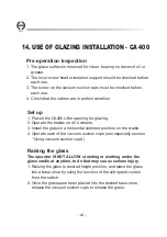
Page 22: ...opening for glazing 2 Operate the brakes on all 4 wheels 3 Install the glass in a horizontal centered position on the cradle 4 Operate each of the vacuum suction cups see especially section Using vacuum suction cups 1 Raising the glass to desired height position and place the glass into a base shoe by using the function of the soft speed control from the switch 2 Once the glass pane been placed in...

Page 23: ...icates that the maximum power of membership range is reached If more than 6 8 pressures were necessary it should be checked immediately as the glass surface and also the cups 3 If during the use of the red security should again be visible due to a loosening of the vacuum it is necessary to immediately press the plunger again 4 To detach the suction cup make sure the load to be lifted is assured Un...

Page 24: ... suction cup prior to its use Examine handle for dents or cracks Examine rubber pads for excessive glaze cuts or roughness 6 Suction cup should only be sued for lifting carrying and holding objects for a short period of time However in the case of long periods of attachment check suction cup regularly to ensure firm adhesion If grip dose not feel sufficiently firm reapply suction cup 7 Do not plac...

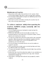
Page 25: ...faces and clean dry without traces of oil or grease 6 The cups and especially rubber discs should be kept clean and free of oil or grease 7 Before each use check the rubber disc relative to any restrictions on functionality due a reduced elasticity due to age wear improper maintenance storage etc 8 Hard rubber or damaged with reduced carrying capacity must be replaced 1 Only the qualified personne...

Page 26: ...ck the levers as the photo 1 2 Place the glass on the vacuum suction cups see instruction page 20 23 3 Loosen carefully the lever A and tilt the cradle as photo 2 Do not tighten the lever A 4 Loosen carefully lever B for tilt the cradle as photo 3 to the desire position and tight the lever B 5 Once all the desire position is set raising the glass softly A B 2 1 3 24 ...

Page 27: ...ush 1 When The Spare Part is out of order When you find there is the abnormal condition happened to the Portable Lifter or the spare part is broken and wish it to be replaced you Must contact the manufacturer to repair it Do not purchase the spare Part and replace it by yourselves 2 Consulting Service If you have any problems of operation and disorder about Portable Lifter please contact the distr...

Page 28: ...396CM Length Width Store Operating 55 x 65CM 26 MAX Capacity Basic Height Lifting Height 150KG 120KG 100KG 60KG 101 x 97CM Glass Crandle Front load Slant Front load Vertical Right Left Side Vertical Glass Crandle K S F Load capacity with Glass cradle in different position front load slant front load in vertical Right Left side load in vertical ...

Page 29: ...K S F K S F 17 Explode View of Motor and Gearbox 27 ...

Page 30: ...K S F K S F 18 Explode View of CA 400 28 ...

Page 31: ...19 Explode View of CRADLE K S F 29 ...

Page 32: ...KSF ...

Reviews: