12
12
EN
ENROLLING
TAMPERS
INSTALLATION
CERTIFICATIONS
To enroll
imago
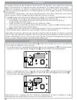
wireless on the system, please follow the procedure here below:
1.
On the
ergo
keypad, browse the programming menù till the ‘Enroll’ mode
2.
Move the front anti-opening switch (
open/close the cover of the
imago
)
3.
On the
ergo
keypad, confirm the S.N. of the device.
If enrolling is successfully made, the red LED on RF PCB module will turns on as confirmation
For any additional information, please see the
lares
programming manual.
The
imago
wireless siren has two protections: against opening the device and against forced removal
from the wall on which was fixed (two switches in series). The siren constantly checks the status of
these two switches and their eventual opening will be communicated to the
lares
. Then, subject
to programming,
lares
may requires the activation of acoustic and luminous signals to report the
attempted sabotage.
The
imago
wireless should be installed in a place hardly accessible to discourage any attempts of
tampering; of course sooner or later having to be reached if non-rechargeable battery replacement
(
if it is powered with the latter
), it must still be accessible for later intervention. The wall bracket must not
show depressions and/or bosses in order not to compromise the operation of tamper mechanism. For a
correct installation, please refer to the ‘Parts identification‘ paragraph and follow the steps here below:
1.
Insert the stainless steel hinges (
included
) and close the nuts (
please not tight
)
2.
Open the polycarbonate cover using a plate srewdriver near the corners.
3.
Remove the metallic undercover, paying attention to not damage the PCBA
4.
Using a drill, bore the base fixing holes
(
the central one is already made to make the installation easier
)
5.
If you wants to power up the device with direct 12Vdc supply, pass the cables through the eyelet
6.
Fix the polycarbonate base with Fishers plug (
included
)
7.
If you chose to use external supply:
A
- Link the alimentation cable to the clamps following the correct polarity
B
- Place and link the 6Vdc - 1.2Ah acid lead battery
• Place and link the non-rechargeable battery pack KSI7207580.000
8.
Verify the correct power up
9.
Re-insert the undercover starting from the top and paying attention to not damage the PCBA
10.
Close the cover
RTTE
1995/5/CE


