10
10
EN
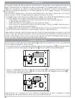
PARTS IDENTIFICATION
7
7
7
11
8
8
7
7
9
10
12
13
14
16
17
23
24
18
19
19
20
21
22
10
2
2
1
3
4
4
6
5
1
Cover
2
Stainless steel hinges (2)
3
Metallic zinc-plated
undercover
4
Screws (2) for fixing the
undercover
5
Eylet for sabotage tamper
activation
6
Transparent base
7
Base locking holes (5)
8
Undercover locking
holes (2)
9
Removal tamper hole
10
Battery base
11
Chock (2)
12
Tamper protection/anti-
tear micro-switch
13
Non-reloadable battery
(KSI7207580.000) connector
14
Power supply terminal blocks
12Vcc (*)
15
Tamper protection:
Anti-opening
16
Buzzer connector
17
PCB - main board
18
PCB - RF interface
19
High efficiency LED (2)
20
Power central LED 1W
21
Cables (2) r/b with faston
22
Exponential Buzzer (120 dB)
23
SN label
24
Eyelet for cable pass-through
(*) The terminal blocks has 4 inputs. Please use only + (positive) and - (negative) for the
power supply. Do not use A and B blocks
15


