sirena da esterno imago - imago outdoor siren
20
TERMINALS (UNIVERSAL VERSION IMAGO ONLY)
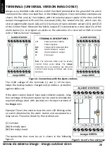
Always use a shielded cable with an end of the shield connected to the ground of the alarm
station and the other one kept free. In the following figure 4 two connection examples are
shown, the first one (a), the simplest, with the external power supply of the siren and the
tamper management with end line resistance (10k), the second one (b), which uses the
siren programmable inputs [AL] and [LI] by means of open collector outputs [O1] and [O2]
of the Control Panel. Moreover the failure output [F] is connected to a zone input [i1] of the
alarm station (i.e. to program an action as the activation of a vocal call or SMS or e‐mail
with a "Battery failure" message).
TERMINALS DESCRIPTIONS
+R
Power positive 13,8Vdc
‐
Power negative
M4
Tamper 24hr balanced 10KΩ
O1
Open Collector 1 output
O2
Open Collector 2 output
i1
Zone input
N.B.
:
The terminals names refer to Ksenia
Control Panel series
lares
. The
imago
Universal siren can interface any Intrusion
Control Panel having terminals with same
functions.
Figure 4. Connections with the alarm stations.
Figure5. Use of a free exchange
The 13,8V voltage of the terminals [+] and [‐] of the siren,
keeps the backup battery charged and provides a protection
against cables cut.
If the alarm station doesn't have open collector outputs, relay
free exchange of the alarm station can be used to simulate the
required voltage (start with positive) on the input terminal of
the
imago
siren.
Example: There’s the need to have the siren LED blinking when
an event scheduled by the alarm station and associated to a
relay occurs. The name shown by the terminals are:
[C] Common
[NA] Normally open
[NC] Normally closed
The connection that must be set is shown in the following
figure 5.

