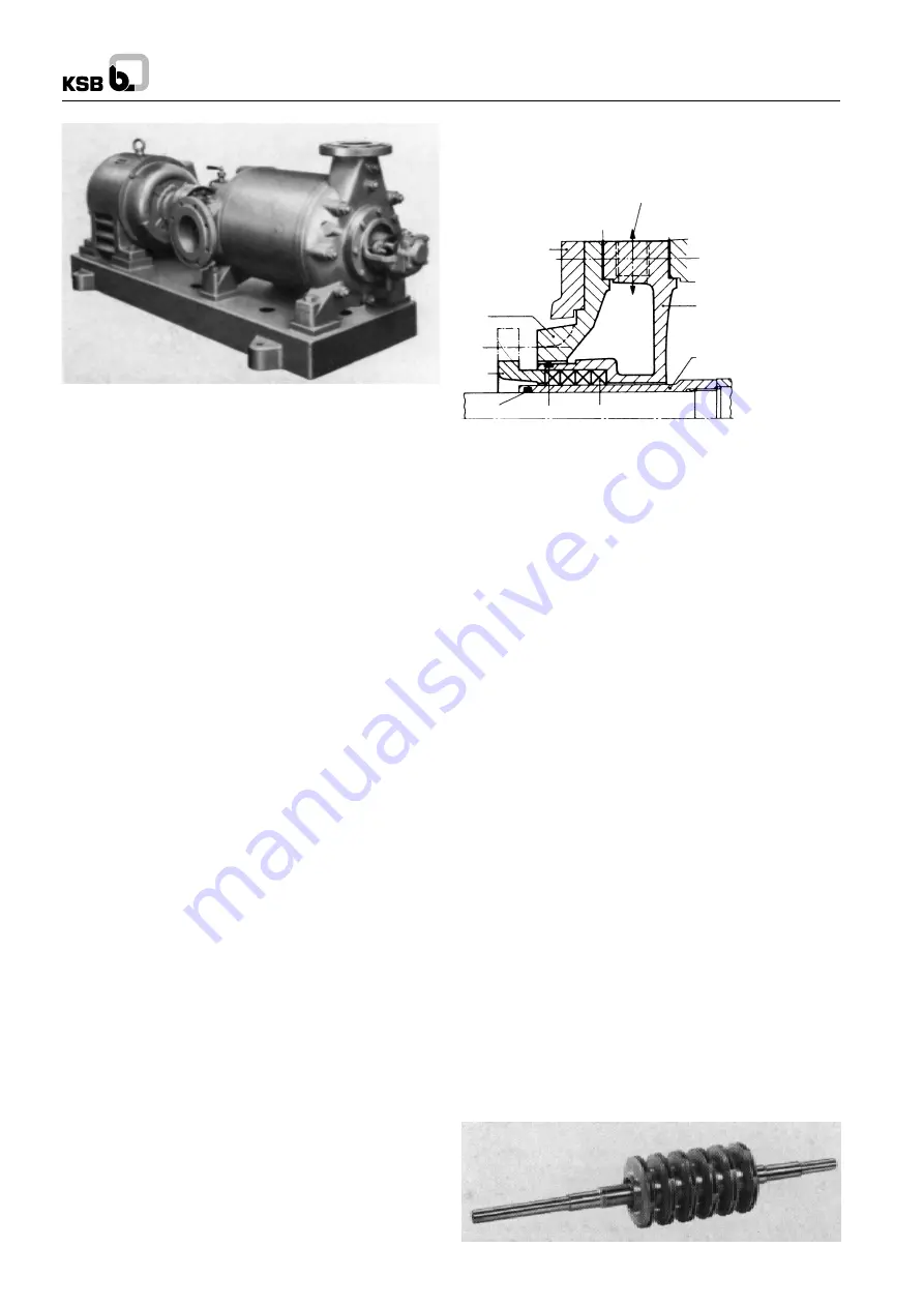
WK
0.
Introduction
WK pumps are High Pressure Horizontal Centrifugal Pumps.
In accordance with the latest state of the art of pump design
and construction, our pumps combine favourable hydraulic
characteristics with a long service life, reliability of operation
and simple maintenance and operation.
A pre-requisite for trouble-free operation of the pumps is the
careful observance of the recommendations contained in this
operating instruction manual. It should therefore, always be at
the disposal of the personnel entrusted with the erection,
maintenance and operation of the pump.
It goes without saying that the pumps should only be operated
under the duty conditions specified (see data sheet). The terms
of our Guarantee naturally apply within this range of conditions.
Our Guarantee will become invalid if the pumps are dismantled,
either completely or partially, without our prior consent. The
first assembly and dismantling of the pump should be carried
out by skilled fitters and erectors, and this also applies to the
initial start-up (commissioning) of the pumping set.
1.
Pump Construction
(For item numbers, see under section 16, Sectional drawings.)
1.1
Casing
WK high pressure centrifugal pumps are single or multistage
centrifugal pumps with a radially split casing. This consists of
the suction and discharge casing (106 and 107) together with
a number of stage casings (108). If the extraction of a given
quantity of the liquid pumped at one of more intermediate
pressures is required, the corresponding stage casings can
be provided with extraction (Bleed off) nozzles. The individual
casing components are sealed off against one another by flat
gaskets (400.2) or by ‘O’ rings (412) and clamped together by
connection rods (905). The diffusers (171.1 and 171.2) are
arranged in the stage casings and in the discharge casing
respectively (108 and 107 respectively). They are centered in
the casings at their outer periphery and secured against
twisting.
The stuffing box housings (451) and bearing housing (350)
are flanged onto the suction and discharge casing respectively
(106 and 107) and attached by studs (902.1). The stuffing box
housings (451) are sealed off from the suction and discharge
casings respectively (106 and 107) by a flat gasket (400.3).
On pumps fitted with special hot water stuffing boxes or with
mechanical seals, the shaft seal is surrounded by a cooling
Fig. 1
water compartment, which is sealed off against atmosphere
by the stuffing box housing cover (165) with flat gasket (400.3)
and O-ring (412.4) (See Fig. 2)
Fig. 2 Stuffing box housing with cooling compartment cover
Depending on the number of stages and on the temperature
of the product pumped, the pump feet are integrally cast onto
the suction and discharge casings (106 and 107) either at the
bottom, or at shaft centerline height. The suction nozzle can
be arranged to point horizontally to the left or right hand side,
or vertically upwards, if the pump feet are arranged at the
bottom of the pump; if they are arranged at shaft centerling
height, the suction nozzle can only be arranged to point
vertically upwards the discharge nozzle points radially upwards
on both types of pump feet arrangement.
In order to achieve a favourable NPSH required, the suction
nozzles on all sizes of pumps are made one nominal size larger
than the discharge nozzles. The flange construction is specified
in the data sheet.
1.2
Rotor
All the rotating components assembled on the shaft make up
the complete pump rotor (See Fig. 3 and 4)
The shaft (210) transmits the torque generated by the drive
onto the impellers. The impellers (230) are mounted is
sequence on shaft (210), and they all point in the same
direction. They are secured against twisting by keys.
The narrow clearance gap between impeller neck and casing
wearing ring (502) at the suction and discharge end of each
impeller prevents the equalization of presure between one
stage and the next.
The shaft (210) is protected inside the pump against attack by
the fluid pumped by means of spacer sleeve (525.1/2) and
distance bushes stage (521). The distance bushes/stage also
serve to locate the impellers axially on the shaft. The shaft
(210) is protected by the shaft protection sleeves (524.1/.2) in
the region of the shaft seal. These protection sleeves are
screwed onto shaft (210) by means of screw threads with
opposed hand to the direction of rotation of the shaft.
Fig. 3 Assembled rotor
412.3
412.4
461.1
452
165
350
400.3
7A/7E
400.3
451
524.2
(524.1)
1


