


13
7.4
Recommendations for installation
Before assembly
-- Verify that pipeline flanges are free from metallic chips and weld
splatter.
-- Verify that pipeline flanges are located on the same centreline and
are parallel.
-- Verify that inside diameter of pipeline flange is in accordance with
the minimum and maximum diameters given by the manufacturer.
-- Verify that nothing hinders the complete moving of the disc during
opening or closing, in particular at the internal weld seams or at the
pipe ends.
-- Pull apart the pipeline flanges to allow valve insertion without
damaging the elastomer liner of the valve.
During assembly
-- Place the disc as spaced apart as possible from the closing
position, but without that disc protrudes past the valve’s body.
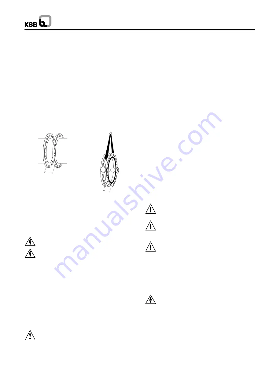
-- Spread the two pipe flanges to obtain sufficient clearance between
flange face and valve seat cheeks.
E + 40 mini
E
Minimum clearance : E + 40mm
E : Face to face valve
(refer to the type series booklet)
-- Insert valve between pipeflanges and center using several tie--rods.
-- Screw up progressively the nuts until metal to metal contact is
achieved between the valve body and pipeline flanges, by making
sure the good centering of the body compared with the flange is
maintained.
-- Operate the valve several times to ensure no valve disc obstruction.
7.5
Actuated valves
Electrical cables may only be connected by qualified personnel.
The applicable electrical regulations (e.g. IEC and national
standards), also for equipment in hazardous locations, must be
observed.All electrical equipment such as actuator, switchboard,
magnetic valve drive, limit switch etc. must be installed in floodproof
dry locations.Voltage and frequency must match the valves stated on
the identity plate.
8
Commissioning/Decommissioning
8.1
Commissioning
8.1.1
General
Prior to commissioning the valve, the pressure, temperature and
material data stated on the valve should be compared to the actual
operating conditions in the piping system to check whether the valve
can withstand the loads occurring in the system.
Possible pressure surges (water hammer) must not be exceed
the highest admissible pressure. Adequate precautions should be
taken.In new pipe systems and especially after repair work, the
system should be flushed with the valves fully open to remove solids,
e.g. weld beads, which may damage the seats.
8.1.2
Operation
The position of the disc is indicated by the pointer of the actuator or by
handle lever. The valves are closed by turning in the clockwise
direction (top view) and opened in the counterclockwise direction.
8.1.3
Functional Check
The following functions should be checked:Before commissioning,
the shut-off-function of the valves should be checked by repeated
opening and closing.
8.1.4
Actuated valves
Adjustable end stops and torque limiter are pre--adjusted in factory.
The customer may have to complete the adjustment on site during the
commissioning, if necessary.
8.2
Decommissioning
During extended shutdown periods, liquids liable to change their
condition due to polymerization, crystallization, solidification etc. must
be drained from the piping system. If necessary, the piping system
should be flushed with the valves fully open.
9.
Maintenance/Repair
9.1
Safety Instructions
Maintenance and repair work may only be carried out by skilled and
qualified personnel.
For all maintenance and repair work, the safety instructions listed
below and also the general notes in section 2 must be
observed.Always use suitable spare parts and tools, even in case of
emergency, otherwise correct operation of the valves cannot be
assured.
9.2
Valve removal from piping and actuator
disconnecting
Identify the valve by identity plate.
Please check what is the relevant spare kit.
Place the disc at 10
°
opening.
The entire valve must be unpressurized and must have cooled
down sufficiently so that the temperature of the medium is lower than
60
°
C, to prevent scalding.
Opening pressurized valves will cause danger to life and
limb!lf toxic or highly flammable substances or liquids whose residues
may cause corrosion by interaction with the air humidity were handled
by the valve, then the valve should be drained and flushed or vented.lf
necessary, wear safety clothing and a face guard/mask.Depending on
the installation position, any liquid remaining in the valve may have to
be removed.
Prior to possible transport, the valves must be flushed and drained
carefully.lf you have any questions please contact your KSB Sales
Office.
lf actuators powered by an external source of energy (electric,
pneumatic, hydraulic) need to be removed from the valves or
dismantled, the energy supply must be shut down prior to starting any
repair work.
Remove the valve from the piping with its actuator.
Do not
damage the liner during removal the valve from the pipe. Therefore,
pull apart the pipe flanges to allow sufficient clearance.
Identify the mounting position of the actuator
Disconnect the actuator and take care of all bolting parts
.


