background image

11 Related Documents

61 of 68

KSB Delta Solo / KSB Delta Eco

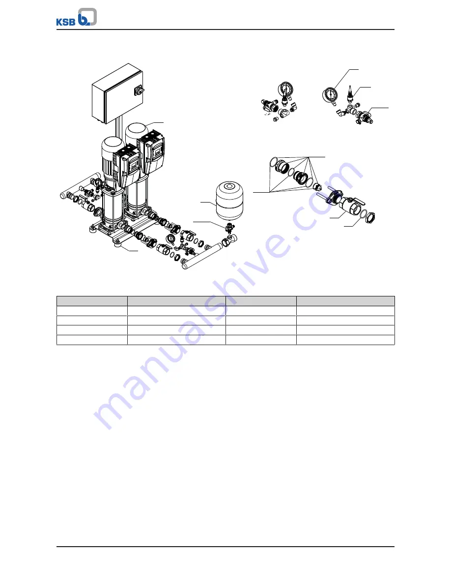
11.1.2 KSB Delta Eco SVP

591

655

595

743.90

743.90

79-2

691

742.02

742.01

743

412

Fig. 44: 

 KSB Delta Eco SVP

Table 27: 

List of components

Part No.

Description

Part No.

Description

79-2

Measuring transducer

655

Pump

412

O-ring

691

Pressure gauge

591

Accumulator

742.01/.02

Check valve

595

Anti-vibration pad

743/.90

Ball/plug valve

The individual parts of the pump set are shown in the product literature of the pump
set.

Summary of Contents for Delta Eco SVP

Page 1: ...Pressure Booster System KSB Delta Solo KSB Delta Eco KSB Delta Solo SVP KSB Delta Eco SVP Installation Operating Manual ...

Page 2: ...contents provided herein must neither be distributed copied reproduced edited or processed for any other purpose nor otherwise transmitted published or made available to a third party without the manufacturer s express written consent Subject to technical modification without prior notice KSB B V Alphen aan den Rijn Nederland 13 09 2018 ...

Page 3: ...nics requirements 11 2 9 3 Interference immunity requirements 11 3 Software Changes 12 4 Transport Temporary Storage Disposal 13 4 1 Checking the condition upon delivery 13 4 2 Transport 13 4 3 Storage preservation 13 4 4 Return to supplier 14 4 5 Disposal 14 5 Description 15 5 1 General description 15 5 2 Designation 15 5 3 Name plate 15 5 4 Design details 15 5 5 Configuration and function 16 5 6...

Page 4: ...play 35 8 1 2 Main screen 38 8 1 3 Settings menu 39 8 1 4 Service interface and LED traffic light function 42 9 Servicing Maintenance 43 9 1 General information Safety regulations 43 9 1 1 Inspection contract 44 9 2 Servicing Inspection 44 9 2 1 Supervision of operation 44 9 2 2 Checklist for inspection 45 9 2 3 Setting the pre charge pressure 45 9 2 4 Replacing the non return valve 46 9 2 5 Mount...

Page 5: ...Braking resistor Takes up the braking power produced during generator operation Certificate of decontamination A certificate of decontamination is enclosed by the customer when returning the product to the manufacturer to certify that the product has been properly drained to eliminate any environmental and health hazards arising from components in contact with the fluid handled Dry running protect...

Page 6: ...inery To install partly completed machinery supplied by KSB refer to the sub sections under Servicing Maintenance 1 3 Target group This operating manual is aimed at the target group of trained and qualified specialist technical personnel ð Section 2 3 Page 8 1 4 Other applicable documents Table 1 Overview of other applicable documents Document Contents Sub supplier product literature Operating man...

Page 7: ...y CAUTION CAUTION This signal word indicates a hazard which if not avoided could result in damage to the machine and its functions General hazard In conjunction with one of the signal words this symbol indicates a hazard which will or could result in death or serious injury Electrical hazard In conjunction with one of the signal words this symbol indicates a hazard involving electrical voltage and...

Page 8: ...the operating limits described in the other applicable documents Only operate pressure booster systems which are in perfect technical condition Do not operate partially assembled pressure booster systems The pressure booster system must only handle the fluids described in the product literature of the respective design variant Never operate the pressure booster system without the fluid to be handl...

Page 9: ...perator user Fit protective equipment e g contact guards supplied by the operator for hot cold or moving parts and check that the equipment functions properly Do not remove any protective equipment e g contact guards during operation Eliminate all electrical hazards In this respect refer to the applicable national safety regulations and or regulations issued by the local energy supply companies If...

Page 10: ...rding EMC compliant installation be observed and followed In accordance with the EMC product standard the EMC requirements to be met depend on the purpose or intended use of the frequency inverter Four categories are defined in the EMC product standard Table 4 Categories of intended use Category Definition Limits to EN 55011 C1 Frequency inverters with a supply voltage under 1000 V installed in th...

Page 11: ...mmunity requirements for a frequency inverter hinge on the specific environment in which the inverter is installed The requirements for industrial environments are therefore higher than those for residential and office environments The frequency inverter is designed such that the immunity requirements for industrial environments and thus the lower level requirements for residential and office envi...

Page 12: ...ta Eco 3 Software Changes The software has been specially created for this product and thoroughly tested Making changes or additions to the software or parts of the software is prohibited This does not however apply to software updates supplied by KSB ...

Page 13: ...se suitable and permitted transport equipment e g crane forklift or pallet jack ü The pressure booster system has been checked for in transit damage 1 Make sure the transport equipment is suitable for safely carrying the indicated load 2 Transport the pressure booster system to the place of installation 3 Attach the pressure booster system to the lifting tackle Lift it off the pallet Dispose of th...

Page 14: ...drying 4 Always complete and enclose a certificate of decontamination when returning the pressure booster system ð Section 13 Page 63 Always indicate any safety and decontamination measures taken NOTE If required a blank certificate of decontamination can be downloaded from the following web site www ksb com certificate_of_decontamination 4 5 Disposal WARNING Fluids handled consumables and supplie...

Page 15: ...508 SVP 48278598 56 1A 50 Hz 3x400V PT 01 2018 1234567 01 123456789 54 16 1 14 13 12 6 11 10 9 8 7 2 5 4 3 Fig 1 Name plate example 1 Type series 8 Dry running protection 2 Design 9 Power supply voltage 3 Number of pumps 10 Power supply frequency 4 Size 11 Maximum current input 5 Number of pump stages 12 Max operating pressure 6 Serial number 13 Enclosure 7 Month of production year of production c...

Page 16: ...binet IP54 Fault message signalling contact per pump Operation signalling contact per pump 5 5 Configuration and function 1 2 3 6 4 5 2 3 6 4 Fig 2 Configuration 1 Terminal box 2 Pump 3 Control unit 4 Membrane type accumulator 5 Manifold 6 Baseplate Design The fully automatic pressure booster system is equipped with vertical high pressure pumps 2 all of which are speed controlled for pumping the f...

Page 17: ... by function The pressure booster system is designed with integrated electronic dry running protection A digital lack of water indicator can be connected to the corresponding contacts During commissioning and after every power failure the pressure booster system fills the piping system slowly to prevent any damage to the piping by surge pressure 5 6 Noise characteristics Pressure booster systems a...

Page 18: ...ed control unit Graphical display with operating panel Three LEDs signalling the operating status Lockable master switch repair switch Motor protection switch per pump One frequency inverter per pump Service interface for KSB ServiceTool 5 8 Dimensions For dimensions refer to the outline drawings of the pressure booster system 5 9 Terminal wiring diagram For the terminal assignment refer to the ci...

Page 19: ...llation WARNING Installation on mounting surfaces which are unsecured and cannot support the load Personal injury and damage to property Use a concrete of compressive strength class C12 15 which meets the requirements of exposure class X0 to EN 206 1 The mounting surface must have set and must be completely horizontal and even Observe the weights indicated NOTE The anti vibration mounts of the pre...

Page 20: ...ings of appropriate size 4 Set the pressure booster system down in its correct installation position 5 Use suitable bolts to firmly anchor the pressure booster system 6 4 Installing the piping Make sure that piping is installed without transmitting any stresses or strains The use of length limited expansion joints see accessories is recommended CAUTION Air pockets in suction line Pressure booster ...

Page 21: ...ducer must be installed if the inlet pressure fluctuation is too high for the pressure booster system to operate as intended or if the total pressure inlet pressure plus shut off head of the pressure booster system exceeds the design pressure The maximum pump discharge pressure at zero flow point is reached in manual mode A minimum pressure gradient of 5 metres is required for the pressure reducer...

Page 22: ...ion is equipped with a second relay 400 V 3 variant with 1 relay DI EN 24V GND DI3 DI2 DI1 24V DICOM AO GND AO AIN2 NO 24V GND COM 24V B1 B2 B3 B4 B5 B6 B7 B8 B9 B10 A1 A2 A3 A4 A5 A6 A7 A8 A9 A10 GND GND AIN1 24V L1 L2 L3 LINE PE U V W MOTOR PTC MOTOR PE 1 2 3 4 BR 6 1 2 Fig 5 Overview of terminal strips for 400 V 3 variant with 1 relay 1 Connection to power supply network and motor 2 Control cab...

Page 23: ...mended NOTE If a residual current device is installed observe the operating manual for the frequency inverter The circuit diagrams for the pressure booster system are included in the control cabinet where they must remain when not in use The product literature of the switchgear and controlgear assembly supplied with the pressure booster system includes a list of the electrical components installed...

Page 24: ...have discharged The terminal wiring compartment is covered by a screwed on housing cover The terminals of the power and motor connection cables are additionally guarded by a protective cover to prevent them from being touched Housing cover Fig 6 Housing cover 1 Remove the cross recessed head screws on the cover 2 Remove the cover Protective cover Fig 7 Prying open the protective cover 1 The protec...

Page 25: ...iant with 2 relays L1 L2 L3 LINE PE U V W MOTOR PTC MOTOR PE 1 2 3 4 BR 6 1 2 DI EN 24V GND DI3 DI2 DI1 24V DICOM AO GND AO AIN2 NO1 24V GND COM1 24V B7 B8 B9 B10 GND GND AIN1 24V NO2 2 24V C1 C2 C3 GND B1 B2 B3 B4 B5 B6 A1 A2 A3 A4 A5 A6 A7 A8 A9 A10 C4 Fig 10 Overview of terminal strips for 400 V 3 variant with 2 relays 1 Mains power supply and motor connection 2 Control cables 230 V 1 variant L...

Page 26: ...he mains power supply and or the motor connection cable through the cable glands and connect the cable s to the specified terminals 2 Connect the line for a PTC connection PTC thermistor to the PTC terminal strip 3 Connecting motor monitoring devices PTC thermistor If no PTC connection is available on the motor side parameter 3 2 3 1 PTC Analysis must be deactivated NOTE IP55 enclosure protection ...

Page 27: ...nnections size A 230 V 1 variant Mains connection Motor connection PTC connection Braking resistor Motor PTC Jumper for IT mains Size B L1 L2 L3 LINE PE U V W MOTOR PTC MOTOR PE L1 L2 L3 N PE 1 2 3 4 5 M 3 BR 6 6 Fig 14 Establishing the mains power supply and motor connections size B Mains connection Motor connection PTC connection Braking resistor Motor PTC Jumper for IT mains ...

Page 28: ...at sink Mind the capacitor discharge time After switching off the frequency inverter wait 10 minutes until dangerous voltages have discharged Jumper in IT mains If the frequency inverter is to be used in an IT mains the relevant IT mains jumpers must be removed 6 7 5 1 Directly connecting the motor cable without motor connector for sizes A and B only DANGER Improper electrical connection Risk of f...

Page 29: ... and W Fig 17 Removing the motor connector 2 Remove the motor connector from the heat sink Fig 18 Inserting and fastening cover 3 Close the opening in the heat sink using the kit accompanying the frequency inverter comprising a cover gasket and bolts screws NOTE IP55 enclosure protection as specified in the technical data is only provided if the cover has been fitted properly ...

Page 30: ...n plug Fig 20 Removing the plug 2 Remove the nut from the plug inside the frequency inverter NOTE IP55 enclosure protection as specified in the technical data is only provided if the O ring has been fitted properly Fig 21 Inserting the O ring 3 Place O ring onto adapter DANGER Pinching of power cable and motor power cable Risk of fatal injury due to electric shock Never damage the insulation of th...

Page 31: ...onnection Ensure that the cable lengths are as short as possible Use different earth bus bars for the control and power motor connection cables The earth bus bar of the control cable must not be affected by currents from the power motor connection cables since this could be a source of interference Connect the following to the earth bus bar of the power motor connection cable Motor earthing connec...

Page 32: ...informed in due time prior to commissioning test running the system 7 1 2 Dry running protection Pressure booster systems are fitted with a dry running protection device A float switch whose volt free contact closes the circuit in upper float position can be connected to the control system as dry running protection Follow the float switch manufacturer s instructions on how to set the float switch ...

Page 33: ...he membrane type accumulator has been checked ð Section 9 2 3 Page 45 1 Set the master switch to 0 unlock all motor protection switches if applicable 2 Provide connection to power supply 3 Open loosen the vent plugs on the pumps refer to the pump s installation operating manual 4 Slowly open the inlet side shut off element and prime the pressure booster system until the fluid to be handled escapes...

Page 34: ...mpare the settings of the motor protection switches with the name plate data re adjust if necessary 9 Check the start and stop pressure re adjust if necessary 10 Test the proper function of the lack of water and dry running protection equipment If not fitted make a relevant note in the commissioning report 11 Vent the pumps for a second time after they have been running for 5 to 10 minutes 12 Set ...

Page 35: ... LED traffic light function The traffic light function provides information about the system s operating status 3 Display Displays information on frequency inverter operation 4 Operating keys Toggling operating modes 5 Navigation keys Navigation and parameter setting 8 1 1 Display OFF OFF MAN AUTO 1 min m h kW A V Hz C bar 1 2 3 4 5 6 7 8 9 Fig 26 Main screen example 1 Operating point display 2 Ty...

Page 36: ...osis S2 x x x Settings S3 x x x and Information S4 x x x The wrench icon shows that you have logged in as a customer AUTO bar Parameter number example Setpoint Closed loop Control Parameter number example Setpoint Closed loop Control 1 3 2 The letter P is used as the first character to identify a parameter number The following characters show the parameter number The wrench icon shows that you hav...

Page 37: ...mode Manual mode must be restarted Table 12 Assignment of keys for manual mode Key Function MAN MAN operating key When switching the operating mode from AUTO to MAN the current operating speed is used as control value Manual 1 3 4 and is displayed accordingly The control point 1 3 10 must be set to Local When switching the operating mode from OFF to MAN the frequency inverter operates at minimum s...

Page 38: ...O Hz AUTO 1 min AUTO kW AUTO A Hz ESC OK ESC OK ESC OK ESC OK 1 2 4 3 5 8 7 6 Fig 27 Selecting and displaying operating values on the main screen 1 Parameter number for speed 1 2 1 1 2 Current speed rpm 3 Parameter number for motor input power 1 2 1 2 4 Current power input of motor in kW 5 Parameter number for motor current 1 2 1 5 6 Current motor current in A ...

Page 39: ...NOTE If the motor standstill heater has been switched on the display alternates between the measured value and the letter H 8 1 3 Settings menu NOTE The standard control panel is designed to be used for simple settings only e g setting the setpoint We recommend using the KSB ServiceTool for more extensive configuration tasks Opening the Settings menu Press and hold the ESC key and press OK AUTO ES...

Page 40: ...dongle NOTE If no keys are pressed for five minutes the system will automatically return to the Standard access level The password can be changed after entering the factory default password Table 15 Parameter for changing the password requires use of the KSB ServiceTool Parameter Description Possible settings Factory setting 1 1 5 Customer Access ID Changing the customer access ID 0000 9999 8 1 3 ...

Page 41: ...dly within a specific time window no additional self acknowledgement is carried out As soon as the alarm condition of a pending alert no longer exists the time interval is started When this interval expires automatic acknowledgement takes place If the alert occurs again within 30 seconds after the time interval has started the interval is extended by one increment Should this not be the case the p...

Page 42: ...PC notebook to be connected via a special cable USB optical The following action can be taken Configuring and parameterising the frequency inverter with the service software Software update Saving and documenting set parameters LED traffic light function The LED traffic light function provides information about the current operating status of the frequency inverter Table 18 LED description LED Des...

Page 43: ...ackle to move heavy assemblies or components WARNING Unintentional start up of pressure booster system Risk of injury by moving parts Make sure the pressure booster system has been de energised before commencing work on the pressure booster system Make sure that the pressure booster system cannot be started up unintentionally WARNING Unqualified personnel performing work on the pressure booster sy...

Page 44: ...igh temperature of fluid handled Damage to the pump Prolonged operation against a closed shut off element is not permitted heating up of the fluid Observe the temperature limits in the data sheet and in the section on operating limits While the system is in operation observe and check the following Check the test run if activated Compare the start and stop pressures of the pumps with the data on t...

Page 45: ...ank and the float valve if applicable Check the overflow for integrity and cleanliness 9 2 3 Setting the pre charge pressure WARNING Wrong gas Danger of poisoning Use only nitrogen to charge the accumulator The pre charge pressure in the accumulator should be set to a value below the set start up pressure The setting can be effected via a valve located under the cover at the top of the accumulator...

Page 46: ...entional start up Comply with the local regulations 2 Close the shut off valve of the pump 3 Place a suitable container under the drain connection 4 Open the drain connections To do so observe the pump s operating manual Fig 30 Removing the screw 5 Remove the screw Fig 31 Screwing the valve s body parts into each other 6 Use a suitable tool to screw the body parts of the non return valve into each...

Page 47: ...k valve into the body Apply a sealant to new O rings See table below Fig 33 Mounting the body 11 Mount the body of the non return valve Fig 34 Loosening the screwed connection of the body parts 12 Use a suitable tool to loosen the screwed connection of the body parts of the non return valve to extend the body length Fig 35 Verifying the alignment 13 Verify the correct alignment Fig 36 Fitting the ...

Page 48: ...valve DN 50 Watts industries IN 050 DN 50 1x Eriks 12192264 2x Eriks 12711459 9 2 5 Mounting the manifold in a mirrored position DANGER Voltage at the pressure booster system Danger to life Prior to opening the device wait at least 10 minutes for any residual voltage to dissipate 1 De energise the pump set and secure it against unintentional start up Comply with the local regulations 2 Close the s...

Page 49: ...fold 6 Remove the complete manifold including valves A A Fig 39 Loosening the EF locknuts A EF locknut 7 Loosen the EF locknuts at the shut off valves by half a turn exposing the O ring B B A Fig 40 Turning the pressure measuring set A Pressure measuring set B Lever of the shut off valve ...

Page 50: ...the pressure measuring set by 90 NOTE For some variants the pressure gauge or a pressure sensor need to be removed to be able to turn the pressure measuring set A A Fig 41 Turning the shut off valves A Shut off valve 10 Turn the shut off valves by 180 Now turn the complete manifold including valves by 180 A Fig 42 Turning the pressure measuring set A Pressure measuring set ...

Page 51: ... 51 of 68 KSB Delta Solo KSB Delta Eco 11 Turn the pressure measuring set by a last 90 12 If the pressure gauge and or pressure sensors have been removed connect them again ð The manifold is now fitted in a mirrored position ...

Page 52: ...ally after acknowledgement reset or when the cause of the malfunction or fault has been eliminated The operator ensures that trouble shooting is performed by authorised qualified specialist personnel who are thoroughly familiar with the operating manual Reset the frequency inverter to the default factory settings before engaging in any fault rectification measures 10 1 Faults malfunctions Trouble ...

Page 53: ...le pump blocked Check replace control cable connections Remove the pump blockage manually Temperature of power electronics or motor winding too high Reduce the ambient temperature by improving ventilation Improve cooling by cleaning the cooling fins Ensure that the intake opening for the fans is not blocked Ensure that the fans are working properly Reduce the power input by changing the operating ...

Page 54: ...ded KSB SuPremE motor data could not be determined Self acknowledging E19 No motor data available The motor data is not set Self acknowledging E20 AMA fault The extended motor data could not be determined Self acknowledging E76 24 V overload Internal 24 V power supply unit overloaded Self acknowledging E77 PumpMeter communication Incorrect PumpMeter communication Self acknowledging E83 Overflow No...

Page 55: ...with current Check swing check valve Motor voltage output is too low at nominal load 380 V at nominal load Check line input voltage enter motor current at 380 V mains voltage fit larger sized motor Heat sink temperature high PCB temperature high Ambient temperature of frequency inverter 50 C Impermissible operating range mind power derating Dirt in external fans Clean fans Heat sink cooling fins d...

Page 56: ...s wired incorrectly interruption short circuit Re wire properly Sensor connected incorrectly actual value failure Connect sensor correctly No main pump recognised in system Define role in multiple pump system Braking resistor Stop ramp time too short Increase ramp time Pump runs in reverse when motor is not supplied with current Check swing check valve Generator operation of pump Impermissible ope...

Page 57: ...cknowledging E75 Limited stop ramp Set stop ramp time exceeded Self acknowledging E76 24 V overload Internal 24 V power supply unit overloaded Self acknowledging E77 PumpMeter communication Incorrect PumpMeter communication Self acknowledging E78 Firmware update for field bus required Module incompatible with main module Self acknowledging E79 Firmware update for HMI required Module incompatible w...

Page 58: ...mers Control terminal wiring errors DigIn AnIn Re wire properly Dynamic overload protection Incorrect motor data set Match motor data to motor used Wrong direction of rotation of the pump Adjust the direction of rotation of the motor via the phase sequence Hydraulic overload Reduce the hydraulic load Pump blocked mechanically runs sluggishly Check pump Motor terminal board wired incorrectly delta ...

Page 59: ...topped by the stop ramp but coasts to a standstill The amount of time this process takes depends on the mass moment of inertia of the system The drive remains disabled during coasting Self acknowledging E102 Pipe flushing mode active Performing the pipe flushing function Self acknowledging E103 Pipe filling mode active Performing the pipe filling function Self acknowledging E104 Maintenance interv...

Page 60: ... SVP 595 655 742 01 742 02 591 79 2 743 90 691 79 2 Fig 43 KSB Delta Solo SVP Table 26 List of components Part No Description Part No Description 79 2 Measuring transducer 691 Pressure gauge 591 Accumulator 742 01 02 Check valve 595 Anti vibration pad 743 90 Ball plug valve 655 Pump The individual parts of the pump set are shown in the product literature of the pump set ...

Page 61: ...3 412 Fig 44 KSB Delta Eco SVP Table 27 List of components Part No Description Part No Description 79 2 Measuring transducer 655 Pump 412 O ring 691 Pressure gauge 591 Accumulator 742 01 02 Check valve 595 Anti vibration pad 743 90 Ball plug valve The individual parts of the pump set are shown in the product literature of the pump set ...

Page 62: ...to time Pump set EC Machinery Directive 2006 42 EC Pump set Electromagnetic Compatibility Directive 2014 30 EU The manufacturer also declares that the following harmonised international standards have been applied ISO 12100 EN 809 EN 60204 1 EN 806 2 Person authorised to compile the technical file Menno Schaap Manager Product Development KSB B V Subsidiary D P Industries B V Kalkovenweg 13 2401 LJ...

Page 63: ...ng carrier plain bearing inner rotor has been removed from the pump and cleaned In cases of containment shroud leakage the outer rotor bearing bracket lantern leakage barrier and bearing bracket or adapter have also been cleaned For canned motor pumps the rotor and plain bearing have been removed from the pump for cleaning In cases of leakage at the stator can the stator space has been examined fo...

Page 64: ... please refer to the circuit diagram Start up pressure pstart bar Inlet pressure monitoring pinl x setting of inlet pressure switch Stop pressure pstop bar Inlet pressure pinl bar Pre charge pressure of accumulator ppre charge bar The system operator operator s representative herewith confirms to have received instructions on how to operate and service the pressure booster system The relevant circ...

Page 65: ...0 IT mains 28 J Jumper 28 K Key to safety symbols markings 7 L LED display 42 M Main screen 35 Mains and motor connection Size A 26 Size B 27 Size C 28 Motor connection 26 Motor connection cable Connect 24 O OK key 37 Operating limits 8 Other applicable documents 6 P Partly completed machinery 6 Power connection cables Control cable 24 31 Routing cables 26 PTC Size A 26 Size B 27 Size C 28 PTC the...

Page 66: ......

Page 67: ......

Page 68: ...KSB B V Kalkovenweg 13 2401 LJ Alphen aan den Rijn Netherlands 1983 821 01 EN ...

Reviews: