7 Servicing/Maintenance
48 of 72
Amarex N
7.5 Reassembling the pump set
7.5.1 General information/Safety regulations
WARNING
Improper lifting/moving of heavy assemblies or components
Personal injury and damage to property!
▷
Use suitable transport devices, lifting equipment and lifting tackle to move
heavy assemblies or components.
CAUTION
Improper reassembly
Damage to the pump!
▷
Reassemble the pump (set) in accordance with the general rules of sound
engineering practice.
▷
Use original spare parts only.
NOTE
Before reassembling the motor section, check that all joints relevant to explosion
protection (flamepaths) are undamaged. Any components with damaged
flamepaths must be replaced. Refer to the "Flamepaths" annex for the position of
the flamepaths.
Sequence
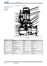
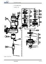
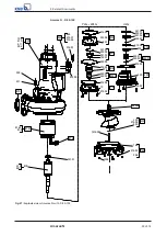
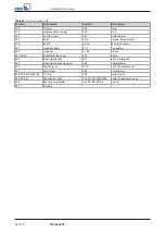
Always reassemble the pump set in accordance with the corresponding general
assembly drawing.
Sealing elements
▪
O-rings
–
Check O-rings for any damage and replace by new O-rings, if required.
▪
Assembly adhesives
–
Avoid the use of assembly adhesives, if possible.
Tightening torques
For reassembly, tighten all screws and bolts as specified in this manual.
7.5.2 Reassembling the pump section
7.5.2.1 Installing the mechanical seal
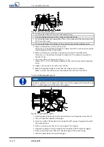
Observe the following points to ensure trouble-free operation of the mechanical
seal:
▪
The shaft surface must be absolutely clean and undamaged.
▪
Immediately before installing the mechanical seal, wet the contact faces with a
drop of oil.
▪
For easier installation of the bellows-type mechanical seal, wet the inside
diameter of the bellows with soapy water (not oil).
▪
To prevent any damage to the rubber bellows, place a thin foil (of approximately
0.1 to 0.3 mm thickness) around the free shaft stub.
Slip the rotating assembly over the foil into its installation position.
Then remove the foil.
ü
The shaft and rolling element bearings have been properly fitted in the motor.
1.
Slide drive-end mechanical seal 433.01 onto shaft 210 and secure it with taper
lock ring 515 or circlip 932.03.
2.
Insert O-rings 412.04/412.35 and 412.15/412.11 into discharge cover 163, and
press them into bearing bracket 330 as far as they will go.
3.
Slide pump-end mechanical seal 433.02 onto shaft 210.
Summary of Contents for Amarex N
Page 62: ...9 Related Documents 62 of 72 Amarex N 9 2 2 Version ULG Fig 33 Wiring diagram for version ULG...
Page 70: ......
Page 71: ......


