background image

7 Servicing/Maintenance

39 of 72

Amarex N

7 Servicing/Maintenance

7.1 Safety regulations

The operator ensures that all maintenance, inspection and installation work is
performed by authorised, qualified specialist personnel who are thoroughly familiar
with the manual.

 DANGER

Sparks produced during servicing work

Explosion hazard!

Observe the safety regulations in force at the place of installation!

Never open an energised pump set.

Always perform maintenance work on explosion-proof pump sets outside
potentially explosive atmospheres only.

 WARNING

Unintentional starting of pump set

Risk of injury by moving parts!

Ensure that the pump set cannot be started up unintentionally.

Always make sure the electrical connections are disconnected before carrying
out work on the pump set.

 WARNING

Fluids handled and supplies posing a health hazard and/or hot fluids handled and
supplies

Risk of injury!

Observe all relevant laws.

When draining the fluid take appropriate measures to protect persons and the
environment.

Decontaminate pumps which handle fluids posing a health hazard.

 WARNING

Hot surface

Risk of injury!

Allow the pump set to cool down to ambient temperature.

 WARNING

Improper lifting/moving of heavy assemblies or components

Personal injury and damage to property!

Use suitable transport devices, lifting equipment and lifting tackle to move
heavy assemblies or components.

 WARNING

Insufficient stability

Risk of crushing hands and feet!

During assembly/dismantling, secure the pump (set)/pump parts to prevent
tipping or falling over.

Summary of Contents for Amarex N

Page 1: ...Submersible Motor Pump Amarex N Pump Sizes DN 50 to DN 100 Motors 2 Poles 002 to 042 4 Poles 004 to 044 Non ATEX Installation Operating Manual...

Page 2: ...nts provided herein must neither be distributed copied reproduced edited or processed for any other purpose nor otherwise transmitted published or made available to a third party without the manufactu...

Page 3: ...ion 12 3 4 Return to supplier 13 3 5 Disposal 13 4 Description of the Pump Set 14 4 1 General description 14 4 2 Designation 14 4 3 Name plate 14 4 4 Design details 15 4 5 Installation types 16 4 6 Co...

Page 4: ...lations 48 7 5 2 Reassembling the pump section 48 7 5 3 Reassambling the motor section 51 7 5 4 Leak testing versions YLG WLG 51 7 5 5 Checking the connection of motor power supply 51 7 6 Tightening t...

Page 5: ...manufacturer to certify that the product has been properly drained to eliminate any environmental and health hazards arising from components in contact with the fluid handled Close coupled design Moto...

Page 6: ...arranty 1 2 Installation of partly completed machinery To install partly completed machinery supplied by KSB refer to the sub sections under Servicing Maintenance 1 3 Target group This operating manua...

Page 7: ...Symbol Description Conditions which need to be fulfilled before proceeding with the step by step instructions Safety instructions Result of an action Cross references 1 2 Step by step instructions No...

Page 8: ...otection against electrical voltage Machine damage In conjunction with the signal word CAUTION this symbol indicates a hazard for the machine and its functions 2 2 General This manual contains general...

Page 9: ...ree flow impeller impeller type F Suitable for the following fluids fluids containing solids and stringy material as well as fluids with entrapped air or entrapped gas Open diagonal single vane impell...

Page 10: ...nd the environment Adhere to all relevant laws Eliminate all electrical hazards In this respect refer to the applicable national safety regulations and or regulations issued by the local energy supply...

Page 11: ...t must be used in potentially explosive atmospheres Special conditions apply to the operation of explosion proof pump sets in accordance with EC Directive 94 9 EC ATEX Especially adhere to the section...

Page 12: ...regional transport regulations Observe the product literature supplied by the lifting accessory manufacturer The load carrying capacity of the lifting accessory must be higher than the weight indicat...

Page 13: ...in the presence of atmospheric humidity or could ignite upon contact with oxygen the pump set must also be neutralised and anhydrous inert gas must be blown through the pump to ensure drying 4 Always...

Page 14: ...2 m 55 47 S1101 2011 2011 DKN 82 2 2U 1 9 2835 4 5 4 4 0 83 400 50 TYPE No Q P2 KSB SAS F 59320 Sequedin Mat No 39023372 TEMP MAX WARNUNG NICHT UNTER SPANNUNG FFNEN WARNING DO NOT OPEN WHEN ENERGIZED...

Page 15: ...n Shaft seal Two bi directional mechanical seals in tandem arrangement with liquid reservoir Impeller type Various application oriented impeller types Bearings Standard bearings Grease packed bearings...

Page 16: ...hain and shackle length 2 m P4 installation parts for guide wire arrangement installation depth3 4 5 m P5 claw P7 chain and shackle length 5 m P4 installation parts for single guide rail arrangement P...

Page 17: ...e pump At the rear side of the impeller the shaft 1 enters the casing via the discharge cover 4 The shaft passage through the cover is sealed towards the atmosphere with a shaft seal 8 The shaft runs...

Page 18: ...TE A separate name plate is included in KSB s scope of supply This name plate must be attached in a clearly visible position outside the place of installation e g at the control panel pipeline or moun...

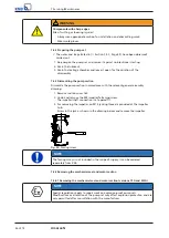
Page 19: ...if necessary 5 2 Checks to be carried out prior to installation 5 2 1 Preparing the place of installation Place of installation for stationary models WARNING Installation on mounting surfaces which a...

Page 20: ...ated in the outline drawing general arrangement drawing 5 2 2 Checking the lubricant level The lubricant reservoirs have been filled with an environmentally friendly non toxic lubricant at the factory...

Page 21: ...d stop it again immediately to determine the motor s direction of rotation 2 Check the direction of rotation Impeller rotation must be anti clockwise seen from the pump mouth The direction of rotation...

Page 22: ...uring times of mortar cartridge Floor temperature Curing time min 5 C to 0 C 240 0 C to 10 C 45 10 C to 20 C 20 20 C 10 5 3 1 2 Connecting the piping DANGER Impermissible loads acting on the flange of...

Page 23: ...ng two parallel tightly stretched guide wires made of stainless steel It attaches itself automatically to the duckfoot bend which has been fitted to the floor NOTE Should site conditions piping layout...

Page 24: ...tening torque M A Nm Guide wire tension P N 50 17 7 3000 50 22 65 170 9 4000 65 220 80 220 14 6000 100 220 5 3 1 4 Fitting the guide rail arrangement 1 or 2 guide rails The pump set is guided into the...

Page 25: ...et rests on the rail ends 6 Tighten nuts 920 01 This expands the clamping sleeves so that they clamp the rails at the inside rail diameter 7 Secure nut 920 01 with a second nut Fitting the guide rails...

Page 26: ...to a torque of 70 Nm 2 Fit profile joint 410 in the groove of the claw This will seal the duckfoot bend pump connection Attaching the lifting chain rope UG1274774 Attaching the lifting chain rope sta...

Page 27: ...e mounting bracket threaded onto the guide rails and lowered down If required alter the position of the crane during installation 1 Guide the pump set over the suspension bracket mounting bracket thre...

Page 28: ...nection point make sure that the number of cores is sufficient for the sensors A minimum cross section of 1 5 mm is required The motors can be connected to electrical low voltage networks with nominal...

Page 29: ...of the pump set particularly the rated current Start up Ensure short start ramps maximum 5 seconds Only start speed controlled operation after 2 minutes at the earliest Pump start up with long start...

Page 30: ...lated in these operating instructions All sensors are located inside the pump set and are connected to the power cable For information on wiring and core marking please refer to the wiring diagrams Th...

Page 31: ...al PE K 1 9 81 56 B2 Connecting the electrode relay Position of the electrode in the motor housing An electrode fitted inside the motor monitors the winding space B2 for leakage The electrode is inten...

Page 32: ...ns For electrical connection observe the wiring diagrams in the Annex and the information for planning the control system The pump set is supplied complete with power cable Always connect all marked c...

Page 33: ...ble ends Potential equalisation conductor Potential equalisation shall be provided for in compliance with EN 60 204 On versions YL and WL the pump casing is designed with an inner thread for a M8 x 20...

Page 34: ...and is equipped with all protection devices The pump has been primed with the fluid to be handled The direction of rotation has been checked The lubricant has been checked only for versions YL and WL...

Page 35: ...start ups per hour Table 14 Frequency of starts Interval Maximum frequency of starts No of starts per hour 30 per year 5000 These values apply to mains start up DOL autotransformer soft starter Freque...

Page 36: ...zing Refer to the maximum permissible fluid and ambient temperature on the name plate and in the data sheet 6 2 4 2 Minimum level of fluid handled DANGER Pump set running dry Explosion hazard Never al...

Page 37: ...onnel Danger of death from electric shock Always have the electrical connections installed by a trained and qualified electrician Observe the IEC 60079 DIN VDE 0100 regulation WARNING Unintentional st...

Page 38: ...n 7 1 Page 39 1 Clean the pump set 2 Preserve the pump set 3 Observe the instructions given in Section 3 3 Page 12 6 4 Returning to service For returning the pump set to service observe the sections o...

Page 39: ...entionally Always make sure the electrical connections are disconnected before carrying out work on the pump set WARNING Fluids handled and supplies posing a health hazard and or hot fluids handled an...

Page 40: ...cables Section 7 2 1 2 Page 40 Visually inspect the lifting chain rope Section 7 2 1 1 Page 40 Check the sensors Section 7 2 1 4 Page 41 Change the lubricant Section 7 2 2 1 4 Page 43 Inspect the bea...

Page 41: ...replaced NOTE If the insulation resistances measured on the motor are too low the winding insulation is defective The pump set must not be returned to service in this case 7 2 1 4 Checking the sensors...

Page 42: ...lubricants can be used to lubricate the mechanical seals Table 18 Oil quality Description Properties Paraffin oil or white oil Alternative motor oils of grade SAE 10W to SAE 20W Kinematic viscosity a...

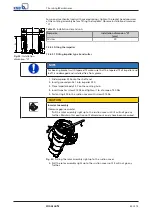
Page 43: ...ing the lubricant a Versions YL and WL for pump size 50 170 and 65 220 b Versions YL WL 2 Place a suitable container under the screw plug WARNING Excess pressure in the lubricant reservoir Liquid spur...

Page 44: ...ubricant 2563 112 Fig 21 Draining the lubricant The suction cover and the impeller have been removed Section 7 4 3 Page 46 1 Place a suitable container under the pump set 2 Move mechanical seal 433 02...

Page 45: ...NING Unqualified personnel performing work on the pump set Risk of injury Always have repair and maintenance work performed by specially trained qualified personnel WARNING Hot surface Risk of injury...

Page 46: ...elevant general assembly drawing 1 Remove suction cover 162 2 Undo and remove the M8 impeller fastening screw The impeller shaft connection is a tapered fit 3 For removing the impeller an M10 jacking...

Page 47: ...h mating ring 433 02 out of intermediate casing 113 5 Remove circlip 932 03 6 Remove primary ring 433 01 7 Pull off mating ring holder 476 8 Take the mating ring out of mating ring holder 476 9 Take O...

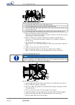
Page 48: ...mbly adhesives if possible Tightening torques For reassembly tighten all screws and bolts as specified in this manual Section 7 6 Page 52 7 5 2 Reassembling the pump section 7 5 2 1 Installing the mec...

Page 49: ...of impeller and shaft is undamaged and installed free from grease 1 Slide impeller 230 onto the shaft end 2 Insert grooved pin 561 into impeller 230 3 Place impeller body 23 7 on the centring hub 4 In...

Page 50: ...s the clearance between the suction cover and the impeller vanes 10 Tighten the suction cover with screws 914 03 11 Rotate the impeller body to check that the impeller turns smoothly Make sure that th...

Page 51: ...DANGER Wrong screws bolts Explosion hazard Always use the original screws bolts for assembling an explosion proof pump set Never use screws bolts of different dimensions or of a lower property class...

Page 52: ...parts Shipping address Mode of dispatch freight mail express freight air freight Refer to the general assembly drawing for part numbers and descriptions 7 7 2 Recommended spare parts stock for 2 years...

Page 53: ...Table 24 Overview of spare parts sets Description Part No Rolling element bearing motor end 321 01 Rolling element bearing pump end 3210 02 Mechanical seal motor end 433 01 Mechanical seal pump end 4...

Page 54: ...Replace worn parts by new ones X X X Defective riser pipe and sealing elements Replace defective riser pipes replace sealing elements X X X Impermissible air or gas content in the fluid handled Contac...

Page 55: ...02 81 59 210 821 818 321 01 970 561 02 General assembly drawing of non explosionproof pump set ULG Table 26 List of components Part No Description Part No Description 100 Casing 550 Disc 162 Suction c...

Page 56: ...pump set YLG non explosionproof pump set WLG Table 27 List of components Part No Description Part No Description 100 Casing 476 Mating ring carrier 113 Intermediate casing 550 Disc 162 Suction cover...

Page 57: ...903 81 2 321 01 210 818 821 412 01 321 932 04 355 355 321 01 932 02 321 02 932 01 412 02 932 04 433 01 476 476 433 01 932 03 412 03 113 914 02 113 321 01 932 02 321 02 932 01 321 476 433 01 433 01 93...

Page 58: ...4 355 355 321 321 01 932 02 321 02 932 01 932 04 476 412 02 476 433 01 433 01 932 03 412 03 113 914 02 113 321 01 932 02 321 02 932 01 321 412 02 476 476 433 01 433 01 932 03 412 03 330 330 914 02 433...

Page 59: ...932 04 412 02 476 433 01 932 03 412 03 13 914 02 355 321 476 433 01 113 321 01 932 02 321 02 932 01 321 412 02 476 476 433 01 932 03 433 01 412 03 330 914 02 330 433 02 230 914 04 550 230 162 914 03...

Page 60: ...Moisture sensor 23 7 Impeller body 81 2 Connector 230 Impeller 81 59 Stator 321 01 02 Radial ball bearing 818 Rotor 330 Bearing bracket 821 Rotor core pack 355 Bearing bracket housing 834 Cable gland...

Page 61: ...9 Related Documents 61 of 72 Amarex N 9 2 Wiring diagrams 9 2 1 Version WLG YLG Fig 32 Wiring diagram for version WLG YLG...

Page 62: ...9 Related Documents 62 of 72 Amarex N 9 2 2 Version ULG Fig 33 Wiring diagram for version ULG...

Page 63: ...4 2 3 3 5 1 2 4 6 F F Q Motor contactor e g T l m canique GV2M GV2 AN 11 KM Motor contactor 3 e g T l m canique LC1 D0910 RH Earth leakage protection relay with separate toroid e g Vigirex RH 328 A Me...

Page 64: ...amepath mm 12 5 12 5 12 5 Inside diameter drilled hole mm 30 142 32 Outside diameter shaft mm 29 9 142 32 Tolerance ISO inside diameter F7 H8 H8 Tolerance ISO outside diameter g6 Tolerance in m inside...

Page 65: ...5 12 5 Inside diameter drilled hole mm 30 152 32 Outside diameter shaft mm 29 9 152 32 Tolerance ISO inside diameter F7 H8 H8 Tolerance ISO outside diameter g6 Tolerance in m inside diameter to DIN IS...

Page 66: ...e 31 Sectional drawings of the mechanical seal Part No Description Sectional drawing 433 01 Mechanical seal bellows type mechanical seal 433 01 932 01 433 02 932 01 Circlip 433 02 Mechanical seal bell...

Page 67: ...me to time Pump set Machinery Directive 2006 42 EC The manufacturer also declares that the following harmonised international standards have been applied ISO 12100 EN 809 EN 60034 1 EN 60034 5 A1 Pers...

Page 68: ...plain bearing inner rotor has been removed from the pump and cleaned In cases of containment shroud leakage the outer rotor bearing bracket lantern leakage barrier and bearing bracket or adapter have...

Page 69: ...measurement 40 Intended use 8 Interference immunity 29 L Leakage monitoring 31 Level control 29 Lubricant 42 Intervals 40 Quality 42 M Maintenance work 40 Mechanical seal 66 Minimum fluid level 36 Mi...

Page 70: ......

Page 71: ......
Page 72: ...KSB SE Co KGaA Johann Klein Stra e 9 67227 Frankenthal Germany Tel 49 6233 86 0 www ksb com 2563 81 15 EN 01503371...

Reviews: