Krone Vario Pack 1510 Operating Manual Download Page 38

V - 8

Basic Settings and Operation

5.8.4 Inserting Twine

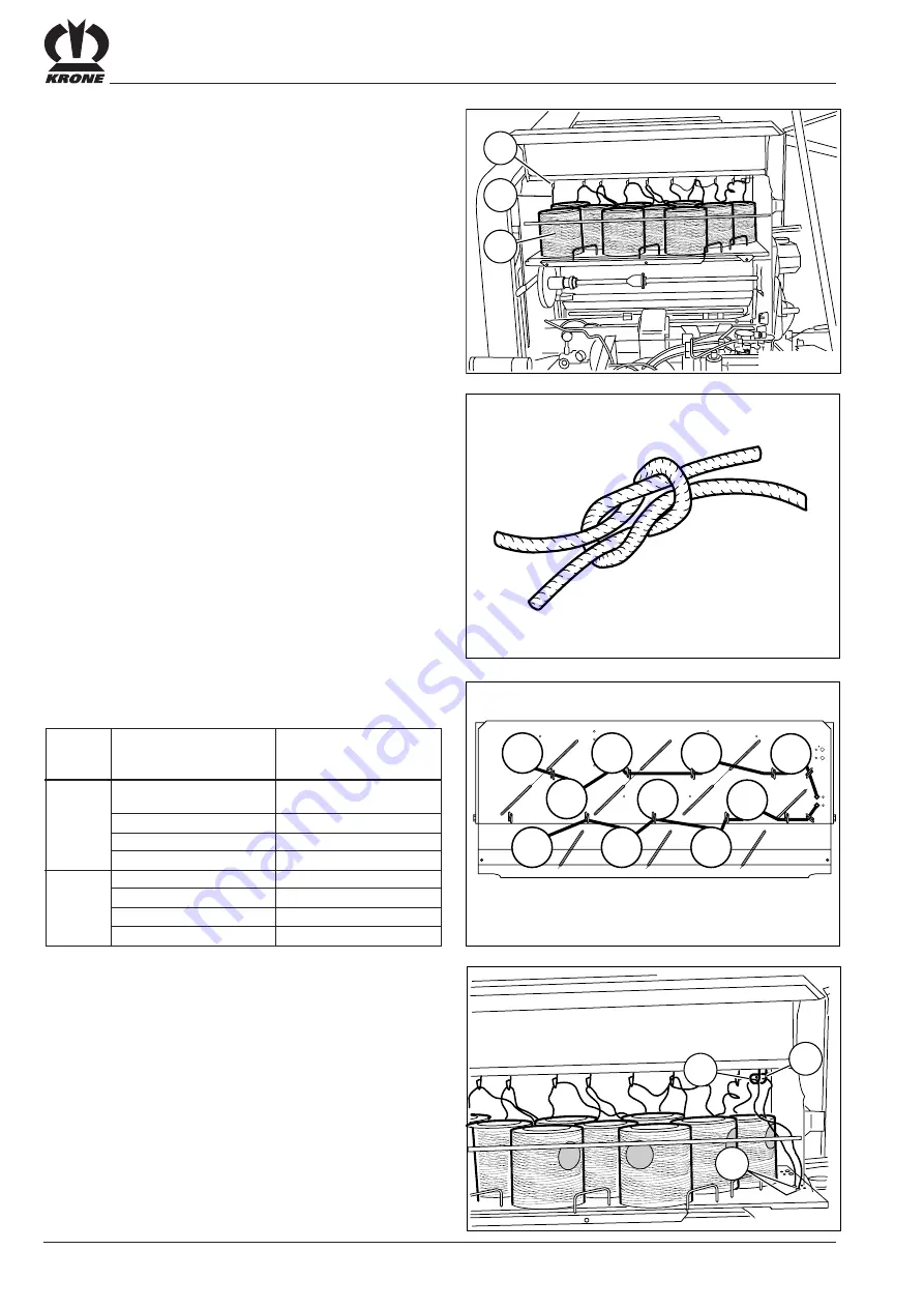
The twine box can hold up to 10 rolls of twine (1).

Threading the twine
Before knotting the roll of twine (1), thread the twine (3)
through the corresponding twine guide (2).

Knot the twine as shown in this example.

end of

with start of

roll

roll

1

4

4

7

7

8

8

10

2

3

3

5

5

6

6

9

The rolls of twine are connected as follows:

Thread the twine downwards through the twine guides
(1) and the front bore holes (2) inside the twine box.

Thread 1 through the back bore hole.

Thread 2 through the front bore hole.

thread 1

(back)

thread 2

(front)

KR-1-009

RBV04150

2

3

1

10

7

4

1

2

3

5

6

8

9

RBV00241

RBV04142

1

1

2

Summary of Contents for Vario Pack 1510

Page 1: ...Operating manual No 766 2 GB Round Baler Vario Pack 1510 Vario Pack 1810 from machine no 541 290 ...

Page 2: ...er side Spelle 01 10 2002 Dr Ing Dr Josef Horstmann Managing Director ppa Dr Ing Klaus Martensen Manager of the engineering and design dep Wolfgang Ungruh Director of Quality Control We declare in our sole responsibility that the product to which this declaration refers corresponds to the relevant basic health and safety requirements of EC Directive 89 392 EEC 3 amending directive of 22 7 93 EC De...

Page 3: ...aling IV 3 5 Basic Settings and Operation V 1 5 1 Pick Up V 1 5 2 Baffle Plate V 2 5 3 Roll type crop guard Special Equipment V 2 5 4 Select baling pressure V 3 5 5 Adjusting baling diameter V 3 5 6 Attaching and Detaching the Bale Ejector V 4 5 7 Floor Conveyor Chain V 5 5 8 TwineWrapping Twine and Net Wrapping V 6 5 9 Net Wrapping Net and Twine Wrapping V 13 5 10 Bale Counter V 18 5 11 Central C...

Page 4: ...II 13 8 8 Cleaning Tensioning Arm at floor conveyor rear VIII 13 8 10 Lubrication VIII 15 9 Winter Storage IX 1 9 1 General Information IX 1 10 Return to Service X 1 10 1 General Information X 1 10 2 Vent Overload Coupling on the PTO Shaft X 2 11 Faults Causes and Remedy XI 1 11 1 General Faults Causes and Remedy XI 1 11 2 Faults Causes and Remedy in the Central Chain Lubrication Device XI 4 A1 Co...

Page 5: ...l Information This operating manual is valid for the Vario Pack 1510 and Vario Pack 1810 round balers starting with serial number 541 290 1 2 2Manufacturer s Address Maschinenfabrik Bernard Krone GmbH Heinrich Krone Straße 10 D 48480 Spelle Germany Telephone 49 59 77 935 0 Fax 49 59 77 935 339 E mail info ldm krone de 1 2 3Certification Declaration of Conformity The requirements of EC Machine Dire...

Page 6: ...is permitted only with the prior approval of the manufacturer The basic requirements in any case are swath form loading of the baling material and automatic lifting by the pick up 1 2 7General Technical Data Road driving is permitted only when the bale chamber is empty and closed Permissible top speed 40 km h 30 km h For machines which have no brakes the pulling tractor s tare weight must correspo...

Page 7: ...570 2850 Pick up width DIN 1950 Bale dimensions diameter approx 1000 1500 1000 1800 width approx 1200 Power requirement approx 36 kW 50 PS 40 kW 55 PS Drive speed PTO shaft 540 U min Max permissible operating pressure of the hydraulic system 200 bar Lighting 12 Volt 7poliger Stecker Control System 12 Volt 3poliger Stecker DIN 9680 Twine Open air storage synthetic twine 400 600 m kg Indoor storage ...

Page 8: ...I 4 General Information ...

Page 9: ...e centres only 2 2 2Failure to Follow the Safety Instructions Failure to follow the safety instructions could result in personal injury and environmental hazards as well as damage to the machine Failure to follow the safety instructions could result in the forfeiture of any claims for damages Failure to follow the safety instructions could result for example in the following hazards risk to person...

Page 10: ...ed 13 Observe permitted axle loads gross weight and transport dimensions 14 Check and attach transport equipment such as lighting warning devices and any protective equipment 15 Actuating mechanisms cables chains linkages etc for remote controlled devices must be positioned in such a way that no movements are unintentionally triggered at any transport or working positions 16 Ensure that implements...

Page 11: ...f PTO shaft when the angle is too large or the PTO shaft is not required 13 Caution The flywheel will continue to rotate for some time even after the PTO shaft has been disengaged Keep clear of the implement during this time Do not do any work on the implement until the machine has come to a complete standstill and the flywheel has been secured using the hand brake 14 Disengage the PTO shaft stop ...

Page 12: ... When replacing working tools with cutting edges use suitable tools and gloves 5 Dispose of oils greases and filters according to regulations 6 Always disconnect the power supply before working on the electrical system 7 If protective devices and guards are subject to wear check them regularly and replace them in good time 8 When doing electrical welding on the tractor and attached implements disc...

Page 13: ...anger notices attached to the machine warn against any dangers The safety instructions are provided in the form of so called warning pictograms Important information on the location of these safety signs and what they mean is given below Familiarise yourself with the meaning of these warning signs The text printed next to the danger sign and its location on the machine indicate where specific haza...

Page 14: ...II 6 Safety left side of the machine 2 3 1Location of Safety Decals on the Machine right side of the machine RP000022 6 7 5 8 9 1 2 4 3 10 RP000019 3 6 7 5 8 9 ...

Page 15: ...e the shut off tap on the cylinder 1 Order No 939 471 1 1x Before puting the machine into operation read and observe the operating instructions and notes on safety 2 The PTO shaft speed may not exceed The hydraulic system operating pressure may not exceed 200 bar Order No 939 100 4 1x 939 100 4 MAX 540 min MAX 200 bar 3 Order No 939 407 1 2x Never reach into the pick up area when the tractor engin...

Page 16: ...II 8 Safety left side of the machine right side of the machine RP000022 6 7 5 8 9 1 2 4 3 10 RP000019 3 6 7 5 8 9 ...

Page 17: ... No 942 196 1 2x While parts are moving never reach into areas where there is a risk of being crushed The tailgate must only be operated if the baler is attached correctly to the tractor Order No 942 360 1 1x 942 360 1 10 ...

Page 18: ...II 10 Safety 2 3 2Location of General Information Labels on the Machine right side of the machine left side of the machine RP200023 6 11 3 5 2 1 10 7 18 9 14 13 8 RP000024 8 12 3 RE LI 6 17 ...

Page 19: ... 1x 5 6 7 8 942 111 0 1x 942 132 0 1x 441 071 2 3 0 bar 441 072 2 3 5 bar 441 074 2 4 5 bar 2x 942 274 0 2x 942 274 0 13 279 985 1 1x 1 2 3 4 5 6 942 215 0 18 942 215 0 1x 9 939 428 2 1x 14 279 120 0 1x 15 924 573 0 2x 16 924 574 0 2x 939 145 1 1x 40 17 278 393 1 10 278 393 1 1x 11 942 356 2 1x 9 942 356 2 95 12 942 357 1 1x 942 357 1 QS Kontrolle frei Datum Unterschrift 939 428 2 ...

Page 20: ...II 12 Safety ...

Page 21: ...safety distance to all moving parts of the round baler during operation This applies especially to the baling material pick up equipment Remove clogs only when the PTO has been switched off and the engine is at a standstill Never stand in the slewing range of the tailgate or underneath the tailgate when it is unlocked During maintenance assembly or repair work inside the bale chamber or to the tai...

Page 22: ...ction free return blue protective cap PTO Shaft Push the PTO shaft 1 onto the tractor PTO shaft The safety mechanism must engage see the operating instructions provided by the PTO shaft manufacturer Secure the PTO shaft guard retaining chains 2 KR 1 080 2 1 RBR01171 1 2 4 3 Set the jack stand in the transport position Crank the support plate 3 upwards until pressure is relieved on the jack stand 1...

Page 23: ...remsventil am Schlep per benötigt The corresponding hydraulic hose 1 is connected to the Bremsventil on the tractor The brake is activated by actuating the Bremspedal Hydraulic Brake Hilfsbremse Für bestimmte Einsatzverhältnisse können Maschinen die sonst für den Straßentransport keine eigene Bremse benötigen mit einer hydraulischen Hilfsbremse ausgerü stet werden Bei dieser Version wird ein zusät...

Page 24: ...sure that the protective plates have been secured the pick up is secured in the raised position and that the bale chamber is locked Before starting ensure that you have perfect visibility on and around the tractor and the round baler Lighting Equipment Connect the lighting unit to the tractor electrical system Check and clean the tail lights 1 and rear reflectors 2 Check and clean the lateral refl...

Page 25: ...draulic system before disconnecting the hydraulic hoses Remove the PTO shaft only if the motor is switched off Remove the ignition key Park the round baler on firm level ground Place two wheel chocks 1 under the wheels to prevent the baler from rolling The wheel chocks are located on both sides of the machine Disconnect the PTO shaft 1 from the tractor Place the PTO shaft 1 inside the PTO shaft br...

Page 26: ...se Disconnect the hydraulic hoses 1 and electrical connecting cable Store these properly in the corresponding receptacle on the twine box Disengage the trailer coupling or pull the pin Drive the tractor away slowly KR 1 147 1 ...

Page 27: ...motor remove the ignition key and disconnect the 12 V supply voltage Should hazardous situations develop switch off the PTO immediately and bring the round baler to a standstill Never let the round baler run if no operating personnel are on the tractor The round baler can only be operated at a PTO speed of 540 r p m When working on slopes always deposit round bales in such a way that they do not m...

Page 28: ...t the round baler setting to prevailing conditions 4 3 Filling the Bale Chamber To attain a consistent bale density inside a round bale the bale chamber should be filled evenly The swath width is an important factor here The swath width is optimal if the swath has exactly the same width as the bale chamber If the swath is wider than this distortion of the round bales may result The round bale will...

Page 29: ...l the wrapping process is complete Stop the towing vehicle until the tying or wrapping procedure has been completed Eject the round bale from the bale chamber Always fully open the rear flap as the cylinders must be fully extended to generate the pressure for the floor conveyor tension Always close the bale chamber and start the next baling process 4 5 After Baling Slacken the bale chamber floor c...

Page 30: ...y a cam type cut out clutch 1 This clutch has been adjusted by the factory and its setting should not be changed without previous contact with the KRONE Service Department Basic Setting X 29 mm Any modification to the cam type cut out clutch will involve the loss of your warranty rights The use of genuine KRONE spare parts is indispensable RP000031 1 X ...

Page 31: ...he pick up can be adjusted only after the baler has been set to the correct height see A 1 2 Basic Setting the gap between the tines and the ground should be approximately 20 30 mm Raise the pick up hydraulically Slacken the nuts 1 and 2 Adjust the height of feeler wheel 4 by moving it in the slotted hole 3 Tighten nurs 1 and 2 Always adjust both sides RP000003 4 1 2 3 RP000028 1 2 For extreme gro...

Page 32: ...ce using the nut 1 RP000034 a b 2 5 2 Baffle Plate Adjust the height and supporting pressure of the baffle plate 1 to crop conditions Basic Setting high swaths position a low swaths position b Baffle Plate Height Remove the linch pin 2 Insert the pin 4 into the desired bore hole from the inside Secure in place using the linch pin 2 Supporting Pressure Hook the spring 3 into the desired bore hole 5...

Page 33: ...ower Slowly rotate the hand wheel counterclockwise until the pressure gauge indicator points to the desired baling pressure Reset the rotation lock VP 1 061 1 3 4 2 RP000036 1 2 5 5 Adjusting baling diameter Medium Baling diameter is preselected using the adjusting segment located behind the front right guard and is set from inside the twine box via the wing nut 2 on the righthand side Baling diam...

Page 34: ...Detach the bale ejector by pulling backwards Attach the bale ejector in reverse order Do installation work only when the machine is at a standstill Switch off the motor Remove the ignition key The tailgate must be open in order to work on the straw trap Make sure that the shut off tap on the left hand tailgate cylinder is set in the closed position The straw trap weighs approximately 40 kg For thi...

Page 35: ...o work on the round baler chain Make sure that the shut off tap on the lefthand tailgate cylinder is set in the closed position To bale extremely dry smooth crops the front floor conveyor chain can be equipped with 6 additional feed slats Note the direction in which the floor conveyor chains move Attach the 6 feed slats to the predrilled rods on the floor conveyor chain 1 KRS 3 099 ...

Page 36: ...nnect the 12 V supply voltage Secure the tractor and round baler against rolling Selecting Binding and Wrapping Material The selection of binding material is important to ensure troublefree use of the round baler and storage High quality binding material also ensures safe handling of round bales during transport 1 knife bar and guide 2 twine wrapping mechanism 3 pressure roller 4 rubber roller 6 t...

Page 37: ...round bale The twine is picked up by the round bale The twine wrapping mechanism 2 feeds the two twine threads over the round bale from inside to outside and back again A sensor on the twine wrapping mechanism signals the final stage of the wrapping process The twine is then cut and the wrapping process is ended 5 8 2 2 Components Twine and Net Wrapping with twine 1 knife bar and guide 2 twine wra...

Page 38: ...Knot the twine as shown in this example end of with start of roll roll 1 4 4 7 7 8 8 10 2 3 3 5 5 6 6 9 The rolls of twine are connected as follows Thread the twine downwards through the twine guides 1 and the front bore holes 2 inside the twine box Thread 1 through the back bore hole Thread 2 through the front bore hole thread 1 back thread 2 front KR 1 009 RBV04150 2 3 1 10 7 4 1 2 3 5 6 8 9 RBV...

Page 39: ...1 holds the net stretcher bar 2 in position Open the twine cleaning flaps 1 Rotate the twine manually at the stepped roller in the working direction see arrow Remove dirt in area 2 Shut the cleaning flaps 1 Rotate the stepped roller in the direction of the arrow until the twine holders 3 move from the outside to the centre starting position The twine holders 3 must move to the centre when the step...

Page 40: ...ust both sides length of baling material distance between the two twine limiters medium short narrow wide medium The spacing between individual twine wraps on the bale can be changed by inserting the baler twine into different grooves of the stepped roller length of choose diameter wrap baling with stepped roller spacing material short large 1 narrow medium medium medium long small 2 wide Thread t...

Page 41: ... times to ensure that the blades cut correctly Be careful not to tighten the brake so much that the rubber coated roller is unable to transport the thread at the start CP400004 4 1 2 2 3 3 Twine brake release setting Move tensioning arm 2 from lower to central position In this position tension spring 3 must not be under tension wire rope 4 must be slightly released Adjusting lever 1 will release t...

Page 42: ... the same position the sensor bracket 1 can be move to the left or the right Undo bolt 4 Move sensor bracket 1 Tighten bolt 5 8 7 Adjusting the Pressure Roller If the baler twine does not feed correctly at the start pressure roller tension can be increased by adjusting the spring 2 Right side Detach spring 2 Detach bolt 3 and screw into one of the upper bore holes Reattach spring 2 Left side Press...

Page 43: ...ler to a complete standstill Switch off the motor remove the ignition key and disconnect the 12 V supply voltage Secure the tractor and round baler against rolling 5 9 2Components 5 9 2 1 Components Net wrapping 1 knife bar and guide 2 connecting link guide 3 pressure roller 4 rubber coated roller 5 net stretcher bar 6 net brake spring 7 brake lever 8 net brake 9 pressure roller spring RP000042 6 ...

Page 44: ...from the net roll over the guide shaft to the net stretcher bar 5 from there it is threaded between the rubber coated roller 4 and the pressure roller 3 into the knife bar area 1 When the wrapping process begins the rubber coated roller 4 feeds the net into the rotating round bale The net is picked up by the round bale The round bale pulls the net from the net roll over the rubber coated roller 4 ...

Page 45: ...ft 3 and the retainer 4 5 9 4Inserting the Netting Roll Pull the flat iron 1 forward Pull the net stretcher bar 2 upwards and lock into the upper connecting link Slide the brake disc 1 and cardboard tube clamp 2 counterclockwise into the cardboard tube and then onto the netting roll mounting shaft as far as possible Thread the netting 2 over the guide shaft 3 to the net stretcher bar 4 Swing the n...

Page 46: ...sing the mounting lever 2 To pull the netting release the brake To do this press lever 1 downwards Place the net brake callipers 3 below the netting roll 5 9 5Setting the Net Brake In the basic setting the tensioning bolt dimension should be a 5 mm If the net gets caught up during baling then tension must be increased on the spring 1 of the net brake The brake spring 1 can be tightened at the eye ...

Page 47: ...1 on the right and left side The net brake setting depends on the type of net being used The net brake should be set so that the net inside the channel projects abt 50 mm from the knife bar after the binding process is complete Always use a speed of 540 rpm for wrapping use the normal operating speed RP16010 1 2 Adjusting the net brake releasing position With linear motor 1 totally run towards the...

Page 48: ...umber of times the bales are wrapped can be set on the right hand side of the machine on the adjusting screw 2 The point 3 of the spring bar should not be positioned on the adjusting screw Insert an Allen key into position 4 on the adjusting screw and unfasten the counter nut 1 please note left handed thread The adjusting screw can be turned by using the Allen key The further the screw is turned t...

Page 49: ...at no water or dust can enter the tank If the lubricant container is empty the central chain lubrication device needs to be bled fill the container hose with oil before connecting it to the pump The pump must be completely free of air before being connected to the system Actuate the pump manually until oil appears RBV05150 1 2 3 Replace filter 2 once a year First remove empty and then thoroughly c...

Page 50: ...for the individual lubrication points Central chain lubrication diagram 5 Floor conveyor rear 5 Floor conveyor rear 4 Floor conveyor front 4 Floor conveyor front 5 Floor conveyor rear 5 Floor conveyor rear 4 Floor conveyor front 4 Floor conveyor front RP000049 When replacing the nozzles it is essential to ensure that the correct sizes are used Each difference in size will double the oil supply exa...

Page 51: ...oth side walls of the machine The distance between the density indicators 2 and bolt 3 must be x 5 mm Adjust at clevis 4 if necessary Lift the tailgate Secure the opened tailgate against unintentional lowering see section 8 6 2 General Release tension from the chain elevator inside the baling chamber Move shut off tap 1 of control valve 2 from position b to position a Pressure is now released from...

Page 52: ...locked into engagement the density indicators should be lifted clear of bolt 2 Adjustment Release nut 3 Release clevis 4 and adjust as required Tighten the nut again VP103011 1 3 4 VP101012 2 a RP000085 1 2 3 4 To obtain uniformly shaped bales it is essential that both baling pressure indicators are set to the same setting value Adjustment Place rail 1 onto tensioning arm 2 and guide roller 3 Dist...

Page 53: ...ting cables to the round baler do not tense during turning or come into contact with the tractor wheels ControlunitBasis 6 1 General Information 1 wrappingstartbutton 2 ON OFF switch 3 control line to baler 4 powersupply Special Safety Instructions When doing welding work on the round baler or tractor with attached round baler overvoltage could cause damage to the electric components of these cont...

Page 54: ...ght the twine and pulls it The twine wrapping or wrapping process runs automatically 6 2 Preparing for Use Attach the control unit on the tractor in a place where it is clearly visible to the driver Connect the power supply 12V Checkforcorrectpolarity Switch on the control unit using the ON OFF switch 2 The motor should run in basic setting If this is not the case 1 Check the power supply RP600005...

Page 55: ...ls 7 Control unit Medium Electro Hydraulic Control unit Medium 7 1 General Information 5 Indicator light for left right side baling pressure 6 Wrapping mode switch net twine 7 without function 8 Wrapping start button 1 ON OFF switch 2 Control line to baler 3 Powersupply 4 Horn Special Safety Instructions When doing welding work on the round baler or tractor with attached round baler overvoltage co...

Page 56: ... this is not the case 1 Check the power supply 2 Check the setting on the baling pressure gauge set to the 0 position 7 3 Operation 7 3 1 Selecting Wrapping Mode Actuate the ON OFF switch 1 Select twine or net wrapping Use switch 6 to select the tying mode Net wrapping Twinewrapping Setting the number of net wraps is on the right hand side of the machine see Selecting the number of bale wraps chap...

Page 57: ...witch 7 and keep it pressed Switch on the control unit using switch 1 A short beep will sound Once the control unit is switched on keep switch 7 pressed for abt 5 seconds this will determine the duration of the extension stroke of the linear motor in this case 5 seconds Release switch 7 another beep will sound In addition to the manual mode the system will now work in the automatic mode too That m...

Page 58: ...describedinChapter Maintenance Sensor bale diameter right Sensor bale diameter left The bale diameter gauge is located at the front end of the roundbaler When the right hand indicator A rises within the set diameter range the lamp 2 should go out When the left hand indicator B rises within the set diameter range the lamp 1 should go out RP600011 2 1 RP 0 018 2 3 0 1 RP 3 002 B A ...

Page 59: ...tructions to avoid accidents and injuries Adjusting the cutter blades Adjustment Undo bolt 5 Turn eccentric 2 until dimension a is at least 2 mm the eccentric is located outside the machine Tighten the bolt 5 8 1 3 Net Wrapping System Unintentional actuation of the net wrapping system must be prevented The cutter blade on the net wrapping system is extremely sharp Extreme risk of injury 8 1 2Adjus...

Page 60: ...e coupling is disengaged Adjust as follows With the tailgate opened dimension a can be increased by slacking nut 6 Tighten nut 6 until a 5 mm a 2 1 3 VPE00002 VPE10001 1 6 4 b 5 8 2 1Adjusting the moment at which the floor conveyor is switched off The moment at which the floor conveyor is switched off is preadjusted at the factory but can be varied by moving limit stop 1 in the slotted hole if par...

Page 61: ...e 2 mm Adjustment Undo the lock nut 3 Adjust the sensor 1 until gap a 2 mm with spring rail 2 in lower position Tighten the lock nut 3 8 3 4Bale size sensor Bale size sensor 1 is located on the right hand side of the machine under the front guard Distance a between sensor and segment 2 should be 2 mm Adjustment Undo the lock nut 3 Adjust the sensor 1 until gap a 2 mm with spring rail 2 in lower po...

Page 62: ...s open secure it at the shut off tap to prevent it from falling After completing maintenance work reattach all protective plates and protective devices properly Avoid skin contact with oil and grease In case of injuries caused by oils seek immediate medical assistance Follow all further safety instructions to avoid accidents and injuries A thread size resistance class is visible on the head of the...

Page 63: ...onveyor drive x x then after every 100 bales pick up drive x x chain tension floor conveyor drive x x at the beginning of the season pick up drive x x after approx 5 bales chain tension roller drive x x pick up drive x x after first time use approx 30 50 operating hours then annually after every season gearbox x oil change check adjust bleed tighten Intervals Machine component Maintenance at speci...

Page 64: ...ral Information Always slacken and tighten the wheel nuts in the sequence shown in the diagram at right Check the wheel nuts 10 operating hours after mounting and tighten if necessary After this check that the wheel nuts are properly seated every 50 operating hours M 10 x 1 0 17 4 5 93 93 M 12 x 1 5 19 4 5 93 93 M 14 x 1 5 22 5 137 137 M 18 x 1 5 24 6 265 245 M 20 x 1 5 27 8 343 294 M 22 x 1 5 32 ...

Page 65: ... Screw in the oil drain screw Fill the gearbox oil approximately 1 0 litres SAE90 API GL 4 through the check hole until it starts to overflow Screw in the oil check screw 8 5 Drive Chains 8 5 1 Special Safety Instructions The drive chains are equipped with protective devices Always reattach or close the protective devices after completing work on the chains 8 5 2General Information Central lubrica...

Page 66: ...p Be careful Risk of pinching Lower the pick up onto the ground Filling Auger Drive The filling auger drive is located on the pick up on the right hand side of the machine length of stretched spring a 30 mm Rotate the nut 1 until a 30 mm RBV05020 2 1 a Rear Floor Conveyor Drive The rear floor conveyor drive is located on the lefthand side of the machine length of stretched spring b 90 mm Loosen lo...

Page 67: ... automatic chain tensioner Roller Drive The roller drive is located on the right hand side of the machine length of stretched spring a 90 mm Rotate the nut 2 until a 90 mm 2 1 a RP A 004 1 Pick Up Packer Main Drive The Pick up Packer main drive is located on the pick up on the left hand side of the machine length of stretched spring a 30 mm Rotate the nut 1 until a 30 mm Packer drive Slacken the s...

Page 68: ...pressure for the round baler hydraulic system via pressure hoses Of the various components the shut off tap 1 on the left hydraulic cylinder deserves special mention It is designed as a safety device to prevent the tailgate from shutting unintentionally Position a The hydraulic cylinder return is blocked The tailgate cannot shut When working inside the bale chamber when the tailgate is open always...

Page 69: ...ylinder Position a park position bleed air from the pressure cylinders Position b working position 8 6 4Replacing the Hydraulic Oil Filter In order to protect the control valves against dirt a hydraulic oil filter 3 is installed at the righthand side of the front cross pipe The filter element needs to be replaced once a year Replacing the filter element Detach filter 1 Replace filter element Inser...

Page 70: ...he wear limit of the bushing inside the ring hitch has been reached the bushing should be replaced The wear limit of the bushing inside the ring hitch 1 is a 43 mm If this value is exceeded the bushing needs to be replaced To minimise wear clean and grease the bushing and ring hitch daily VP 1 007 a ...

Page 71: ...onveyor chains 8 9 1Shortening the rear floor conveyor chain Before chain length can be checked the rear tensioning arms must be cleaned see Section 8 8 Open the tailgate 1 fully Secure the tailgate using the shut off tap 3 see also Section 8 6 2 If the distance a between the tailgate 1 and the roller chain is greater than 220 mm the roller chain needs to be shortened Slacken the floor conveyor Se...

Page 72: ...shortened as described above The chain tensioning lever must be in Position a after the roller chain has been shortened To shorten the chain 1 a rail 2 is detached as follows Remove the wire pins 1 on both sides Detach the rail 2 Remove two chain links 3 Connect the roller chain with a chain connect link KRS 1 201 1 2 2 1 3 KRS 1 202 1 a b ...

Page 73: ...rvals for the PTO shaft are shown in the diagram at right For additional information refer to the operating instructions provided by the PTO shaft manufacturer Alle Intervallangaben Betriebsstunden Definition of Terms Term Lubricant Location Amount Special Notes grease all purpose grease lubrication nipple approx remove excess grease two strokes from lubrication nipple grease gun lubricate use veg...

Page 74: ...loor conveyor right left 5 guide shaft front top on the tensioning device right left 2 tailgate cylinders right left 2 bearing for floor conveyor shaft right 1 bearing for spiral roller right 1 floor conveyor drive left 1 bearing for spiral roller left 1 chain drives floor conveyor drive leftcentral lubrication pick up drive right and left central lubrication roller drive right central lubrication...

Page 75: ...VIII 17 Maintenance 942 357 1 8 10 2 Lubrication Points on the Round Baler right hand side ...

Page 76: ...VIII 18 Maintenance 9 942 356 2 95 8 10 3 Lubrication Points on the Round Baler left hand side ...

Page 77: ...ainted parts with anti corrosion agent Use only a suitable vehicle jack to jack up the round baler Make sure that the machine is in a secure position when jacked up Jack up the round baler to prevent damage to the tyres tyre damage may occur when the round baler is left standing in the same position for extended periods Protect the tyres against outside influences such as oil grease direct sunshin...

Page 78: ...IX 2 Winter Storage ...

Page 79: ... observe all other specific safety instructions 10 1General Information Before returning to service start the binding or net wrapping mechanism manually and turn the mechanism by hand Check the starter systems of the twine or net wrapping mechanism Grease all lubrication points and lubricate the chains Wipe away any grease which oozes out of the bearings Check the oil level in the main drive gear ...

Page 80: ...PTO Shaft friction clutch only Following extended downtimes overload coupling surfaces 2 may stick to the contact surfaces Vent the overload coupling before use Undo the bolts 1 crosswise Turn the PTO shaft manually Tighten the bolts crosswise KR 0 151 1 1 2 ...

Page 81: ... oil and grease In case of injuries caused by oils seek immediate medical assistance 11 1General Faults Causes and Remedy Remedy Insert hydraulic hose into the corresponding linkage Separate swathes Reduce forward speed Drive slower when starting the baling process until the acquired crop is rotating inside the bale chamber Check the drawbar setting and adjust if necessary Raise the baffle plate P...

Page 82: ... is not transported at the start Netting has incorrect dimensions The idler is not being pressed against the V belt or the free running end inside the actuating wheel jamming Netting roles have not been inserted correctly into the pick up system and or the roller brake mechanism is set incorrectly Netting has not been inserted properly into the wrapping mechanism Dirt in front of and on the starte...

Page 83: ... caught on the cutter blades Wrapping mechanism starter cylinders are bent Net stretcher bar not functioning Hydraulic hose not connected Sides are too full or baling pressure is too high Net stretcher bar has been folded downwards The net is hanging too wide downwards Check the brake setting Check the setting of the cutter blades Check wrapping mechanism replace if necessary Rotate net stretcher ...

Page 84: ...n the pump area Clean Pump is not being pressed at full stroke Adjust in accordance with the operating manual Pump valve closing incorrectly Detach clean or replace Replace with recommended oil Clean or replace all measuring valves Repair or replace Drive with thicker oil Reduce pump lift Pump does not run Repair adjust or replace Main pipe is torn Repair or replace No oil in the system Bleed syst...

Page 85: ...ery The words in parentheses indicate the storage location on the machine during transport 1 bale ejector pallet 2 Spacer Vario Pack 1810 twine box 3 small parts twine box 4 linkage pick up 5 U bracket twine box 7 springs pick up 8 springs with clamp bolts twine box 9 rail twine box 10 clamping sleeve twine box 11 nuts twine box 12 safety foil twine box 13 spray paint can twine box 14 PTO shaft ba...

Page 86: ... wheel chocks under the wheels to prevent the baler from rolling Take parts 1 out of the twine box RBV01170 1 2 3 Depressurise the tractor hydraulics Connect hydraulic hoses 1 2 and 3 to the tractor hydraulics according to colour Remove mounting parts 2 3 from the bale chamber ...

Page 87: ...Risk of accidents Secure the open tailgate to prevent it from closing unintentionally Rotate the shut off tap 1 in the return of the left hand lifting cylinder into position a Remove mounting parts 1 2 from the bale chamber RBV0116A 2 1 2 1 RBV01150 VP 1 057 b 1 a ...

Page 88: ... Press the holding plates outwards Place the bale ejector 3 between the holding plates 2 Set the pins in the top bore hole 1 on the holding plates 2 Secure the pins using the washer 3 and roll pin 4 Tighten the screw connections 1 2 on the holding plate 1 2 VP700014 3 VP700008 VP700007 1 2 RP200087 Pre mount the bale ejector 1 with U spacer 2 ...

Page 89: ...the screw 1 with washer 2 and spring 3 into the bale ejector bore hole 4 Insert the M8x120 screw 5 in bale ejector bore hole Tighten the nut 1 until a 65 mm Do not tighten the screw Repeat this procedure on the righthand side VP 00 002 3 1 2 VP 00 001 2 4 1 5 3 RP000083 1 a 2 ...

Page 90: ... onto the tailgate studs 2 and secure the pins using the washer 3 and roll pin 4 RBV03190 1 3 2 Slide linkage 1 onto the studs on the righthand and lefthand sides of the frame 2 VP700009 1 2 X X VP700021 VP700021 VP 1510 linkage 1 X 1921 mm VP 1810 linkage 1 X 2196 mm RBV03210 1 3 4 2 ...

Page 91: ...re in place using the washer and linch pin 4 Tighten the nut 4 until the bale ejector swings after the placing of the bale reliably into the basic position Shut the tailgate Rotate the shut off tap 1 in the return of the lefthand lifting cylinder into position b Switch on the tractor hydraulics Set the control valve for shut tailgate to lower VP 1 057 b 1 a 2 1 VP700017 Install the spacer 1 with f...

Page 92: ...0 operating hours A1 3 Adjusting Drawbar Height To ensure optimum pick up of baling material the drawbar height must be adapted to the type of tractor being used In working position the lateral front guard 1 should be rather horizontal to the ground The height of the ring hitch should then be matched to the height of the tractor hitch The use of other tyres can require a slightly different adjustm...

Page 93: ...baler to the tractor Take up the shortest operating position for the PTO shaft Pull apart the PTO shaft Slide the PTO shaft 1 onto the tractor PTO shaft Slide the PTO shaft with the overload protection feature 2 onto the machine shaft Measure the overlap Complete length adjustment in accordance with the operating instructions provided by the manufacturer of the PTO shaft RBV01010 1 VP 1 035 1 2 ...

Page 94: ...th overload protection feature onto the machine shaft until the safety mechanism engages or the PTO shaft can be fastened refer to the operating instructions provided by the manufacturer if the PTO shaft A1 4 2 Installing the PTO Shaft Hook the PTO shaft support bracket 2 to the PTO shaft holder 1 KR 1 080 2 1 RBV02240 2 1 RP 99 012 2 1 ...

Page 95: ...r using the fastener 2 RBV01080 2 1 Slide the hose bracket 5 through the slots on the drawbar 6 Fasten the hose bracket to the drawbar using clamps 4 screws 1 washers 2 and self locking nuts 3 RBV01020 2 1 Draw the hydraulic hoses 2 through the hose bracket eyelet 1 RP A 026 1 2 3 4 6 5 ...

Page 96: ...A 12 Appendix A1 6 Lighting System Install the three unit lamps 1 on the right and left rear of the round baler with the lamp facing backwards and secure the cable with the cable band 2 RP000059 1 2 ...

Page 97: ... sw br ws bl ws sw rt 3 6 12 11 10 9 8 7 2 1 BR BL BR BR BL BL BR BL Platine Krone Nr 303 138 Schalter on off Taster Binden Start S2 S1 S5 S6 S3 S4 M1 Motor Binden Start Ader bezeichnung Stecker bezeichnung 1X Ader bezeichnung DIN Stecker für Spannungs versorgung 3 2 Anzeige Links Anzeige Rechts H1 H2 ROT SCHWARZ 82 Signal geber 1 P3 P4 x1 5 x1 4 x1 2 x1 3 P5 x1 1 x1 7 x1 11 x1 6 x1 13 x1 8 x1 9 x...

Page 98: ...A 14 Appendix ...

Page 99: ...A 15 Appendix ...

Page 100: ...brik Bernard Krone GmbH Heinrich Krone Straße 10 D 48480 Spelle Postfach 11 63 D 48478 Spelle Phone 049 0 59 77 935 0 Fax 049 0 59 77 935 339 Internet http www krone de eMail info ldm krone de konsequent kompetent ...

Reviews: