


LOADING AND SECURING
100
Operating instructions • Load Carrier • 505410638-02 • 07/2019
Locking position
1
2
3
4
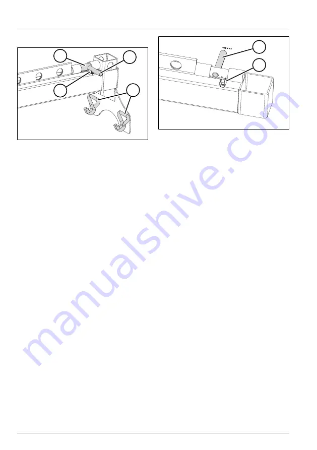
Fig. 8-12:
Multi Block beam lock
1
Retainer bolt
2
Locking lever
3
Fastening hooks
4
Clamping bracket
In the locking position, the retainer bolt is
located in the hole in the square profile.
The locking lever is found on the clamping
bracket. It locks the Multi Block beam.
Inserting the Multi Block system
► Tilt the plug-in bracket towards the
vehicle floor.
► Guide the fastening hooks into the
lashing holes of the Multi Lock external
frame
(see "8.7.1 Using the Multi-Lock ex-
► Insert the second plug-in bracket in the
same hole position on the other side of
the vehicle.
1
2
Fig. 8-13:
Pulling out the locking lever
1
Locking lever
2
Clamping bracket
► Pull the locking lever from the clamp-
ing bracket.
► Push the retainer bolt completely in to-
wards the centre of the Multi Block
beam.
► Insert the Multi Block beam into the
square profiles of the plug-in brackets.
► Move the retainer bolt to the lock posi-
tion.
► Press the locking lever into the clamp-
ing bracket.
ü
The Multi Block system has been in-
serted.
Removing the Multi Block system
► Release the locking lever.
► Remove the Multi Block beam.
► Remove the plug-in brackets from the
Multi Lock external frame.
ü
The Multi Block system has been re-
moved.