Krone 1 000 245 Original Operating Instructions Download Page 61


Operation


61 


9.8


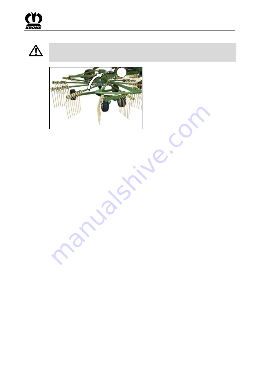
Move the hoop guards to transport position. 


Warning - Crush hazard! 

Effect: Injury to hands 
Do not hold onto hoop guards to swivel within range of the rotating points. 


SW700071_1

1


Fig. 29 


•  Lower rotor arms into working position. 
•  Turn off the tractor and secure it against the possibility of rolling back. 
•  Fold over the hoop guard (1) from working position to transport position. 


Summary of Contents for 1 000 245

Page 1: ...Original operating instructions Rotary Rake Swadro TC 640 from serial no 1 000 245 Order no 150 000 686 03 en 26 09 2018 ...

Page 2: ...ow on our sole responsibility that the Machine Rotor Rake Type Swadro TC 640 to which this declaration refers is in compliance with the following relevant provisions of EC Directive 2006 42 EC machines The undersigned Managing Director is authorised to compile the technical documents Spelle 01 08 2017 Dr Ing Josef Horstmann Managing Director Design Development Year of manufacture Machine no ...

Page 3: ... 3 4 8 Operational safety Technically perfect condition 14 3 4 9 Danger zones 16 3 4 10 Keeping safety devices functional 18 3 4 11 Personal Protective Equipment 18 3 4 12 Safety signs on the machine 19 3 4 13 Traffic safety 19 3 4 14 Parking the machine safely 20 3 4 15 Consumables 20 3 4 16 Sources of danger on the machine 21 3 4 17 Dangers associated with certain activities Work on the machine ...

Page 4: ...ne to the tractor 48 8 3 Connecting the hydraulic lines 49 8 4 Lighting connection 50 8 5 Install the PTO shaft 51 8 6 Using the safety chain 52 8 7 Swivelling parking support into transport position 54 9 Operation 55 9 1 Locking releasing stop cock 55 9 2 Removing the tine protections from the tine tips 56 9 3 Lowering Outrigger Arms into Working Position 56 9 4 Swivel tine arms to working positi...

Page 5: ... the Gearboxes 83 12 4 Deviating Torque 84 12 4 1 Testing the Screws on the Tines 84 12 4 2 Torque of Wheels on the Running Gear 84 12 5 Tyres 85 12 5 1 Checking and maintaining tyres 85 12 6 Replacing the tine arms in case of repair 86 12 7 Replacing the tines in case of repairs 88 13 Maintenance lubrication 89 13 1 Lubrication Points on the Universal Shafts 89 13 2 Lubrication Points on the Mach...

Page 6: ... personnel qualification refer to chapter entitled Safety Personnel Qualification 2 5 How to use this document 2 5 1 Directories and References Table of contents headers The table of contents as well as the headers in this instruction are used for quick navigation in the chapters Index directory In the index directory you can find information on the desired subject via catchwords which are in alph...

Page 7: ...Document In addition to standard equipment accessories kits and versions of the machine are described in this document Your machine may deviate from this document 2 5 6 Means of representation Icons in the text In this document the following means of representation are used Action step A bullet point designates an action step you have to perform as for example Set the left outside mirror Sequence ...

Page 8: ...on step Tighten screws with torque key with specified tightening torque Direction of motion Direction of travel opened closed enlargement of display detail Framings dimension line dimension line limitation reference line for visible parts or visible mounting material Framings dimension line dimension line limitation reference line for covered parts or covered mounting material Laying routes LH Lef...

Page 9: ...ct Injuries serious material damage Measures for hazard prevention Caution CAUTION Type and source of hazard Effect Damage to property Measures for risk prevention Notes with information and recommendations Note Note Effect Economic benefit of the machine Measures to be performed ...

Page 10: ... 2808 foot ft Power kilowatt kW 1 3410 horsepower hp Pressure kilopascal kPa 0 1450 pound per square inch psi megapascal MPa 145 0377 bar non SI bar 14 5038 Torque newton meter Nm 0 7376 pound foot or foot pound ft lbf 8 8507 pound inch or inch pound in lbf Temperature degree Celsius C Cx1 8 32 degree Fahrenheit F Velocity meter per minute m min 3 2808 foot per minute ft min meter per second m s 3...

Page 11: ...rupt the proper operation For this reason unauthorised modifications shall exclude any liability of the manufacturer for consequential damage The intended use shall also include the adherence to the operating maintenance and repair conditions set by the manufacturer 3 2 Reasonably foreseeable misuse Any use beyond the intended use see chapter Safety Intended use is regarded as improper use and is ...

Page 12: ...be taken 3 4 Basic safety instructions Non compliance with the safety instructions and warnings Non compliance with the safety instructions and warnings may result in injuries and damage to the environment and property 3 4 1 Importance of the operating instructions The operating instructions are an important document and a part of the machine They are aimed at the user and contain safety relevant ...

Page 13: ...has the stipulated driving licence 3 4 3 Children in danger Children cannot assess danger and behave unpredictably As a result children are especially at risk Keep children away from the machine Keep children away from consumables Especially before starting up and moving the machine ensure that there are no children in the danger zone 3 4 4 Coupling When tractor and machine are not correctly conne...

Page 14: ... fall off the machine and get run over Ejected objects may strike and injure passengers Never let people ride on the machine 3 4 8 Operational safety Technically perfect condition Operation only when the machine has been started up correctly If the machine is not started up correctly according to these operating instructions the operational safety of the machine is not ensured As a result accident...

Page 15: ... and safeguarding the machine Immediately eliminate potential causes of damage for example heavy soiling or tighten slack screws If possible repair the damage according to these operating instructions In the case of damage which may affect operational safety and cannot be repaired according to these operating instructions Have damage repaired by a qualified service centre Technical limit values Wh...

Page 16: ... the machine Do not switch on the drives and engine until there is nobody in the danger zone The safety clearance is 30 metres in front of the machine while in operation 5 metres in front of the machine when at a standstill 3 metres on either side of the machine 5 metres behind the machine Before working in front of and behind the tractor and in the danger zone of the machine Shut down and safegua...

Page 17: ... safety devices are fitted and in the protection position Ensure that there is nobody in the danger zone of PTO shaft and universal shaft Switch off the drives if they are not necessary Danger zone universal shaft People may become caught by the universal shaft pulled in and seriously injured Observe the operating instructions of the universal shaft Provide the section tube and universal shaft gua...

Page 18: ... equipment is for example Suitable protective gloves Safety boots Tight fitting protective clothing Hearing protection Protective goggles Specify and provide personal protective equipment for the particular job Use only personal protective equipment which is in proper condition and offers effective protection Adjust personal protective equipment to the person for example the size Remove unsuitable...

Page 19: ... and on the ground If the driver does not consider changed handling characteristics he may cause accidents Observe procedures for driving on roads and in fields see chapter Driving and transportation Dangers if machine is not prepared properly for road travel If the machine is not prepared properly for road travel serious accidents may occur with traffic Before driving on roads prepare the machine...

Page 20: ...nsuitable operating materials Operating materials that do not correspond to the requirements of the manufacturer may impair the operational safety of the machine and cause accidents Only use operating materials which meet the requirements For information on requirements relative to operating materials refer to chapter Technical Data Operating Materials Environmental protection and disposal Consuma...

Page 21: ...ing liquids are under high pressure Hydraulic oil Liquids under high pressure may penetrate the body through the skin and cause serious injuries If a damaged pressure system is suspected immediately contact a qualified service centre Never search for leaks with bare hands Even a pin sized hole may cause serious injuries Keep body and face away from leaks If liquids penetrate the body immediately c...

Page 22: ... the machine All other maintenance and repair work may be performed by a qualified service centre only Raised machine and machine parts The raised machine may accidentally drop roll away or overturn and crush or kill people Do not stand under the raised machine First put the machine down Before performing any work under the machine securely support the machine see chapter Safety Securely supportin...

Page 23: ...even the wheel rim could explode and or burst see chapter Technical Data When fitting the wheels tighten the wheel nuts to the stipulated torque see chapter Maintenance Tyres 3 4 19 Behaviour in hazardous situations and when accidents occur Neglected or incorrect procedures in hazardous situations may obstruct or prevent the rescue of people in danger Difficult rescue conditions will impair the ch...

Page 24: ... to movement of the machine or machine parts If the machine is not supported securely the machine or machine parts may roll fall or drop As a result people may be seriously injured or killed Before working on or under raised components Securely support machine or machine parts To securely support the machine or machine parts Shut down and safeguard the machine see chapter Safety Shutting down and ...

Page 25: ... Securely Supporting Raised Machine and Machine Parts Shut down and safeguard the machine refer to chapter Safety Shutting Down and Safeguarding the Machine Observe the intervals for oil level check oil change and filter element change refer to chapter Maintenance Maintenance Table Use only oil qualities quantities mentioned in the consumables table refer to chapter Technical Data Consumables Clea...

Page 26: ... machine as this would impair its full functional capability Hazard warnings are attached to the machine in the relevant areas to warn against any dangers The safety instructions are provided in the form of so called warning pictograms Important information on the position of these safety signs and what they mean is given below GL 1 2 4 5 6 5 RH LH RH LH RH LH 3 RH LH TC640 001_01 3 RH LH 7 Fig 1 ...

Page 27: ...machine may be destroyed or forcibly ejected If the maximum permitted operating pressure is exceeded hydraulic parts may be damaged As a result people may be receive serious or life threatening injuries Observe the permitted PTO speed Observe the permitted operating pressure 3 Order No 939 472 2 2x in case of hydraulic width adjustment design 2 939 472 2 Danger due to impact Risk of death due to s...

Page 28: ...Safety 28 GL 1 2 4 5 6 5 RH LH RH LH RH LH 3 RH LH TC640 001_01 3 RH LH 7 Fig 2 RH right hand machine side LH left hand machine side ...

Page 29: ...ing injuries caused by a flashover if machine parts come too close to power transmission lines Maintain the prescribed safe distance from power transmission lines 7 Order no 27 021 591 0 1x L 27 021 591 0 Danger caused by non locked regulating valves of the tractor There is a risk of accidents if the regulating valves on the tractor are not locked To prevent functions being triggered accidentally ...

Page 30: ...rson 3 6 3 Attaching Safety Labels and Information Labels Note Attaching a label Effect Adhesion of label The attachment area must be clean dry and free from dirt oil and grease 3 6 4 Contact Maschinenfabrik Bernard Krone GmbH Co KG Heinrich Krone Strasse 10 D 48480 Spelle Germany Telephone 49 0 59 77 935 0 Head Office Fax 49 0 59 77 935 339 Head Office Fax 49 0 59 77 935 239 Spare parts domestic ...

Page 31: ...ulated in all countries When transporting the machine the country specific regulations for using the safety chain 2 are binding 3 Support jack The support jack 3 ensures that the machine is stable when it is not hitched to the tractor 4 Wheel chocks Wheel chocks 4 secure the machine against rolling away Two wheel chocks 4 are mounted on the right hand machine side 5 Overload protection The star ra...

Page 32: ...Machine Description 32 4 Machine Description 4 1 Machine overview TC640 002_1 1 2 3 4 5 6 7 8 9 20 10 11 12 13 14 15 16 17 18 19 Fig 4 ...

Page 33: ...sis 3 Wheel chock 13 Tine arm 4 Frame rear 14 Running gear 5 Outrigger arm 15 Main gearbox 6 Hoop guard 16 Overload protection 7 Universal shaft drive 17 Universal shaft rotor drive 8 Universal shaft bracket 18 Rotor 9 Support jack 19 Rotor gearbox 10 Frame front 20 Document storage tube ...

Page 34: ...sking questions concerning the machine or ordering spare parts be sure to provide type designation vehicle ID number and the year of manufacture To ensure that these data are always available we recommend that you enter them in the fields above Note Authentic KRONE spare parts and accessories authorised by the manufacturer help to ensure safety The use of spare parts accessories and other devices ...

Page 35: ...e star ratchet couplings of the overload protection systems can also engage if the speed is low or when approaching the rotors A vibrating noise results The torque is then transferred by pulsation The brief engaging of the star ratchet couplings does not affect the function of the machine To prevent an early wear of the overload protection system switch of the P T O shaft if the vibrating noise ca...

Page 36: ... arms in transport position The maximum height of 4 m must not be exceeded B H L TC640 003 Fig 7 Dimensions in transport position Height with tine arms rigid 3 550 mm Height with tine arms folding 3 350 mm Height with maximum extended working width 3 800 mm Length 4 820 mm Length including steering 5 395 mm Width with 10 75 15 3 10 TL tyres 2 540 mm Dimensions in working position Height 1 600 mm L...

Page 37: ... can be defined Machine equipment series Lower link hitch Cat I and Cat II Tine arms rigid Series Number of arms per rotor 10 Number of double tines per arm 3 Rotor diameter 2 700 mm Lighting Series Warning panels Series Universal shaft Wide angle Equipment of the machine version Tine arms rigid Tine arms folding Machine equipment country specific requirement Safety chain min 89 kN 20 000 lbf Airb...

Page 38: ...ns Dispose of used consumables according to statutory provisions Designation Filling quantity Specification Initial filling ex works Rotor gearbox 0 5 l Fluid gear grease GFO 35 RENOLIT SO GFO 35 Main gearbox 0 5 l SAE 90 Wiolin ML 4 SAE 90 Biodegradable consumables on request 5 3 Tyres Tyres Tyre designation Tyre pressure Main running gear 10 0 75 15 3 10 TL 1 5 bar Rotor chassis 16x6 50 8 10 PR ...

Page 39: ...n Float position red 1 Lowers the machine from transport position to working position Headland position Pressure red 1 Raises the machine from working position to headland position Float position red 1 Lowers the machine from headland position to working position From working position to transport position Switch off PTO drive Pull the operating cable and keep it under tension Pressure red 1 Raise...

Page 40: ...pter Safety must have been read and followed see chapter Safety Basic safety instructions WARNING If the safety routines are not adhered to people may be seriously injured or killed To avoid accidents the safety routines in the chapter Safety must be read and followed see chapter Safety Safety routines WARNING Risk of injury due to the unsecured machine rolling away If the machine is not secured a...

Page 41: ...sion with the trailer coupling Effect Damage to the tractor or machine Depending on the type of tractor the top link of the tractor and or the universal shaft of the machine could collide with the trailer coupling To prevent damage it may be necessary to detach the trailer coupling For further information refer to the tractor manufacturer s operating instructions 7 3 Connecting the Lower Link SW70...

Page 42: ... lower links if necessary The shortest position is reached when the PTO shaft end of the tractor and the drive journal of the machine are at the same height horizontal Park the machine on the support jack Switch off the tractor remove the ignition key and carry it with you and secure the machine against rolling away Disassemble the universal shaft Attach the universal shaft half with the wide angl...

Page 43: ... machine runs diagonally to the tractor Tasks on the steering may only be performed by service technicians dealers SW700078_1 1 2 Fig 11 If the swather is not running in the centre behind the tractor on a level street this can be controlled by adjusting the transverse suspension arms 1 Loosen the counter nut 2 Adjusting transverse suspension arm Steering rod shorter directs machine further to the ...

Page 44: ...r arms are fully extended In order to achieve the shortest possible distance between tine arm and lifting cylinder press tine arm towards outrigger arm Check the dimension X between the outrigger arm 1 and the tine arm 2 If the dimension is X 100 mm the setting is correct If the dimension is not X 100 mm the distance must be adjusted To do this Dismount the countersunk screw 5 and the spacer washe...

Page 45: ...ls shows in the direction of travel If necessary drive up until the running direction of the guide wheels shows in the direction of travel The rotor inclination is set via guide wheels on the chassis individually for each rotor When performing basic setting of rotor inclination the tines 2 must have a certain distance X to the ground 1 The following distances must be met when performing basic sett...

Page 46: ...ons WARNING If the safety routines are not adhered to people may be seriously injured or killed To avoid accidents the safety routines in the chapter Safety must be read and followed see chapter Safety Safety routines Check prior to start up to ensure that The length of the universal shaft is adjusted see section Universal shaft in Start up Driving straight ahead with the machine attached is corre...

Page 47: ...rom the ground In order to prevent swivelling of the machine during transport or operation the lower suspension arms must be secured by limiting chains or bars CAUTION Collision with the trailer coupling Effect Damage to the tractor or machine Depending on the type of tractor the top link of the tractor and or the universal shaft of the machine could collide with the trailer coupling To prevent da...

Page 48: ...t damage it may be necessary to detach the trailer coupling For further information refer to the tractor manufacturer s operating instructions Note In the following description one assumes that the machine after final assembly is in the transport position TC640 004 Fig 16 Connect the machine according to the operating instructions of the tractor manufacturer to the lower links raise it slightly an...

Page 49: ...stem Effect Damages to the machine When connecting the quick couplings ensure that these are clean and dry Note chafing areas or points of contact Note Connect hydraulic hoses correctly The hydraulic hoses are marked with numbers and coloured dust caps Switch the control units on the tractor to float position Depressurise the hydraulic system on the tractor and the machine Shut down and safeguard ...

Page 50: ...t circuits TC640 006 2 3 1 1 Fig 18 The lighting system is connected via the 7 pin connection cable 1 To do this Insert the 7 pin plug of the connection cable 1 into the relevant socket 2 of the tractor Insert the 7 pin connection cable plug 1 into the appropriate socket 3 of the machine Position the cable so that it will not come in contact with the wheels ...

Page 51: ...ch the tractor always observe the chapter entitled Adjusting the length of the PTO shaft 2 SW700083 3 3 1 1 Fig 19 Switch off the engine and remove the ignition key Install the PTO shaft 1 on the machine side wide angle on machine side Rotate the PTO shaft support 2 upwards Then slide PTO shaft onto the PTO of the tractor In doing this ensure that the sliding pin is securely engaged Secure the PTO...

Page 52: ... it does not touch the tractor wheels or other parts of tractor or machine Note Using the safety chain Attachment of the safety chain is not stipulated in all countries Shut down and safeguard the machine see chapter Safety Safety routines Shutting down and safeguarding the machine The safety chain is used as an additional safety precaution for trailed devices should they become detached from the ...

Page 53: ...Start up 53 1 SW9000042_1 Fig 21 Install the safety chain 1 on the machine ...

Page 54: ... 22 Raise the machine until the parking support 1 can be swivelled to the rear Turn off the tractor and secure it against the possibility of rolling back Pull the tension bar 2 swivel the parking support 1 to the rear by 90 and fix it in place in this position by using the tension bar ...

Page 55: ... may be seriously injured or killed To avoid accidents the safety routines in the chapter Safety must be read and followed see chapter Safety Safety routines CAUTION Do not drive in reverse when using the machine for work Effect Damage to the machine The machine is designed to travel forwards Never reverse while the machine is in switched on and in working position Lift rotors first 9 1 Locking re...

Page 56: ...hut down and safeguard the machine see chapter Safety Safety routines Shutting down and safeguarding the machine 2 1 SW700065 Fig 25 Switch on the tractor To relieve the locks 1 actuate the single action control unit at the tractor and pressurise the hydraulic cylinders To release the locks 1 pull the actuating rope 2 and keep it tensioned Set the single action control unit red 1 of the tractor to...

Page 57: ...Shutting down and safeguarding the machine 9 4 1 With rigid tine arms design SW9070082 1 2 3 3 1 Fig 26 Lower outrigger arms into working position Switch off tractor and secure it against rolling away Loosen the tension spring 1 from the tine 2 also loosen rotor locking device if necessary and hinge it in the fastening hole 3 ...

Page 58: ...ng from the front Pull the linch pin 1 Pull out the bolt 2 CAUTION When swivelling the tine arms into working position turn the rotors so that the tine arms do not collide with the guard Swivel the tine arm 3 into working position NOTICE The bolts may collide with the rotor axle if they are not inserted from above and secured Insert the bolt 2 from above Secure the bolt with the linch pin 1 Make s...

Page 59: ...g position Warning Crush hazard Effect Injury to hands Do not hold onto hoop guards to swivel within range of the rotating points SW700068_1 1 2 Fig 28 Swivel the hoop guard 1 to the outside into working position and allow the locking 2 to lock in place ...

Page 60: ...le using the machine for work the machine may be damaged Choose the minimum curve radius so that the tractor does not touch the guards for rotors Ensure there is no one in the working range of the machine Raise lower links by approx 100 mm the height from lower link pinions to ground is approx 630 mm Raise outrigger arms into headland position Switch on universal shaft at low engine speed Increase...

Page 61: ...ury to hands Do not hold onto hoop guards to swivel within range of the rotating points SW700071_1 1 Fig 29 Lower rotor arms into working position Turn off the tractor and secure it against the possibility of rolling back Fold over the hoop guard 1 from working position to transport position ...

Page 62: ...g down and safeguarding the machine 9 9 1 With rigid tine arms design 4 6 5 5 4 SW9070083 Fig 30 Lower outrigger arms into working position Switch off tractor and secure it against rolling away To prevent the rotors from turning unhook the tension spring 4 from the fastening hole 5 and hook it on the tine 6 rotor locking device if necessary ...

Page 63: ...king direction until the folding tine arms are also extended outwards Pull the linch pin 1 Pull out the bolts 2 Swivel the tine arms 3 into the transport position it may be necessary to turn the rotor to prevent the swivelling tine arms 3 from colliding with the guard Insert the bolt 2 and secure with the linch pin 1 Notice Check whether the folding tine arms 3 on both rotors are extended outwards...

Page 64: ...Switch on the tractor To relieve the lockings move the single acting control unit 1 into the float position To raise the lockings 1 pull the operating cable 2 and keep it tensioned Actuate the single acting control unit 1 until the outrigger arms have been raised into the transport position Release the operating cable Actuate the single acting control unit 1 until the lockings 1 on the right and l...

Page 65: ...ed at less than 2 m in transport position or when the machine is switched off The tine guards are located on the front supports right and left side of the machine Raise the rotor arms into transport position Turn off the tractor and secure it against the possibility of rolling back Insert the tine guards 1 onto the tines Repeat this process for the other machine side ...

Page 66: ...ollowed see chapter Safety Safety routines WARNING There is a risk of accidents if the control valves on the tractor are not locked If the control valves are not locked machine components may be activated unintentionally This can result in serious accidents To prevent functions being triggered accidentally the control valves on the tractor must be switched to neutral and locked during road transpo...

Page 67: ...pletely retracted for working width adjustment version the machine is in the transport position the retaining bolts are correctly engaged in the lockings 1 all hydraulic control units are in neutral position the tine guards 2 have been plugged onto the tines located in transport position below 2 m the lighting system works the lower links are lowered to a height of 60 cm to the ground to comply wi...

Page 68: ...rious injuries or death Never move the outrigger arms from working position to transport position or from transport position to working position as long as the machine is positioned across an incline KS102325 Fig 35 For the version with trailing guide wheels In order to prevent the machine from drifting off when driving on the slope the trailing guide wheels must be fixed refer to chapter Settings...

Page 69: ...y of rolling away Secure the machine against the possibility of rolling away by means of wheel chocks 8 To swivel the parking support 1 downward pull the bolt 2 swivel parking support downward until the bolt locks Lower the lower links until the parking support is on the ground Disconnect universal shaft 3 and lay it down on the support 4 Uncouple hydraulic hoses 5 and insert them into the support...

Page 70: ...ollowed see chapter Safety Basic safety instructions WARNING If the safety routines are not adhered to people may be seriously injured or killed To avoid accidents the safety routines in the chapter Safety must be read and followed see chapter Safety Safety routines WARNING Working in the area of the rotor tines Injuries to eyes due to rotors tines Wear protective goggles when working in the vicin...

Page 71: ...lower links until the lower link pinions are approx 63 cm above the ground Switch off the tractor and secure it against rolling away Fold up the lock 2 To increase the space between the tines and the ground turn the crank handle 1 to the right To reduce the space between the tines and the ground turn the crank handle 1 to the left To secure the crank handle fold down the lock 2 ...

Page 72: ...r the rotors until the guide wheels are just above the ground Shut down and safeguard the machine refer to chapter Safety Safety routines Shutting Down and Safeguarding the Machine Loosen the counter nut 1 CAUTION Damage to the machine if the threaded spindle is set to a dimension of X 750 mm Set the threaded spindle to a dimension of X 750 mm Set the desired working width via the threaded spindle...

Page 73: ...he working width if the tractor is switched off and the tines are in contact with the ground Only set the working width of the rotor arms in headland position In order to lift the rotors to the headland position actuate the single action control unit red 1 In order to increase the working width actuate the double action control unit blue 2 In order to reduce the working width actuate the double ac...

Page 74: ...ear are inserted into one of the seven boreholes in the hole pattern Pos I reduce rotor inclination Pos II increase rotor inclination Do not step under the raised rotors Only raise the outrigger arms as far as necessary to perform the changeover work To set rotor inclination dismount the rear guide wheels and move them in the hole pattern For better orientation observe the basic setting of rotor i...

Page 75: ...Settings 75 Note If the forage is heavy adjust the inner running gear as low as possible ...

Page 76: ...nclination The transversal inclination in the direction of travel changes when one of the rear guide wheels is set higher or lower than the other guide wheel Fine adjustment by the screw on the oblong hole 3 reduce the distance between ground and running gear increase the distance between ground and running gear Do not step under the raised rotors Raise the rotor arms only far enough to be able to...

Page 77: ...der to prevent the machine from drifting off when driving on the slope fix the trailing guide wheels To do this Loosen counter nut 5 Press guide wheel to the outside until the stop is reached and hold it Unscrew the screw 4 until it rests against the screw 3 Tighten counter nut 5 ...

Page 78: ...Settings 78 This page has been left blank deliberately ...

Page 79: ...llowed see chapter Safety Safety routines 12 1 Spare Parts Warning Using non approved spare parts Effect Danger to life serious injuries or loss of warranty claims as well as exclusion of liability Use only authentic KRONE spare parts and accessories authorised by the manufacturer The use of spare parts accessories or additional equipment not manufactured tested or approved by KRONE will exclude a...

Page 80: ...after 50 hours Every 50 hours After 1000 ha Rotor gearbox Maintenance free permanently lubricated with grease Main gearbox Oil level check X Oil change X Tyres Check tyres for cuts and breaks visually X Check tyre pressure X X X Wheel nuts X X Crown nut chassis X X Tighten screws nuts All screws X X Screws on the tines X X X Check the locking of the transport position X X ...

Page 81: ...tightened via hexagonal socket Tightening torque in Nm unless otherwise stated A thread size stability class can be seen on screw head A Stability class 5 6 8 8 10 9 12 9 Tightening torque Nm M4 3 0 4 4 5 1 M5 5 9 8 7 10 M6 10 15 18 M8 25 36 43 M10 29 49 72 84 M12 42 85 125 145 M14 135 200 235 M16 210 310 365 M20 425 610 710 M22 571 832 972 M24 730 1050 1220 M27 1100 1550 1800 M30 1450 2100 2450 ...

Page 82: ...27 x 2 1148 1635 1914 M30 x 1 5 800 2100 2650 12 3 3 Metric Thread Screws with Countersunk Head and Hexagonal Socket NOTICE The table applies only to countersunk screws with hexagonal socket and metric thread which are tightened via hexagonal socket Tightening torque in Nm unless otherwise stated A thread size stability class can be seen on screw head A Stability class 5 6 8 8 10 9 12 9 Tightening...

Page 83: ...rs This table applies only to locking screws with external hex in connection with copper seal ring for bleed valves made of brass with shaped seal ring Thread Locking screw and viewing glass with copper ring Ventilation breather filter made of steel Bleed valve made of brass Ventilation and breather filter made of brass Steel and cast Aluminium Steel and cast Aluminium Maximum tightening torque Nm...

Page 84: ...ing to the Maintenance Table When having released the screws remove the nut apply adhesive high strength on the threading overhang of the screw lift the tines on the tine end and tighten the nut to the torque specified below 12 4 2 Torque of Wheels on the Running Gear SW700079_1 Fig 43 Check locknut According to the maintenance table ...

Page 85: ...imum permitted pressure is reached let out the air align tyres lubricate the tyre heels and pump up the tyre again Detailed information about how to fit tyres onto agricultural machinery can be obtained from the tyre manufacturers 12 5 1 Checking and maintaining tyres 1 KS 0 034 6 2 4 5 3 Fig 44 When loosening and tightening the wheel nuts observe the order indicated in the illustration Check the ...

Page 86: ...Maintenance 86 12 6 Replacing the tine arms in case of repair SW700041_1 6 3 1 2 Fig 45 ...

Page 87: ...er before installation with high strength adhesive Apply glue high strength Part No 939 042 0 on the front of the control arm shaft 4 Mount the tine arm 3 and secure with clamping sleeves 5 While installing the tine arm make certain that the cam follower roller is inserted into the running track of the cam track Note The cam follower roller is securely inserted into the running track when barely a...

Page 88: ...n tine remove all tines in front of the broken tine Remove the broken tine Mounting new tine Insert tine holder into tine In doing so make sure that the tine holder is positioned according to the figure Slide tine with tine holder on tine arm Guide hexagon head screw with detent edged washer and disc from below through tine holder and tine arm Apply adhesive high strength on threading overhang of ...

Page 89: ... injured or killed To avoid accidents the safety routines in the chapter Safety must be read and followed see chapter Safety Safety routines Prerequisite Outrigger arms are in working position see chapter Lowering Outrigger Arms into Working Position Shut down and safeguard the machine see chapter Safety Safety routines Shutting down and safeguarding the machine 13 1 Lubrication Points on the Univ...

Page 90: ...Maintenance lubrication 90 13 2 Lubrication Points on the Machine 1 2 3 5 6 7 4 TC640 012 3 2 4 4 4 6 5 Fig 48 ...

Page 91: ...Maintenance lubrication 91 Lubricate the lubrication points every 20 operating hours 1 2 3 4 5 6 7 8 For the main chassis steered version Lubricate the lubrication points every 250 operating hours 9 ...

Page 92: ... quickly as possible Danger of infection Physicians who are not familiar with this area must consult appropriate information from a competent medical source Check the hydraulic hoses at regular intervals and replace them if damaged or worn Only original KRONE spare parts are permitted to be used as replacement lines as they correspond to the technical requirements of the manufacturer Before the pr...

Page 93: ...outines in the chapter Safety must be read and followed see chapter Safety Safety routines Note Tighten the locking screws on the gearboxes with the prescribed tightening torques refer to chapter Maintenance Tightening Torques for Locking Screws and Bleed Valves on Gearboxes Interval for oil level check and oil change refer to chapter Maintenance Maintenance Table Oil quality quantity see Consumab...

Page 94: ... of oil refer to chapter entitled Technical Data of Machine Operating Materials Oil Change Collect escaping oil in a suitable container Screw out oil drain plug 2 and drain the oil Screw in the oil drain plug 2 Unscrew the inspection screw 1 Top up new oil until the control hole 1 is reached Screw in the inspection screw 1 Note The used oil must be disposed of correctly ...

Page 95: ... accidents the safety routines in the chapter Safety must be read and followed see chapter Safety Safety routines 16 1 Tine loss safeguard KS 0 098 3 2 4 1 5 Figure 50 Mounting the tine loss safeguard The tine loss safeguard for the double coil spring tines consists of a cable two cable clamps two coach bolts washers and lock nuts each Secure the cable 1 with the cable clamps 2 onto the rotor tine...

Page 96: ...ins 1 with a spring type slotted straight pin 3 and a washer 2 at the suspension arm seats Attach chain hooks 4 to the tractor Select chain length according to desired max lowering level Note Spare tine loss safeguards Order No 153 479 0 Chain for height restriction of suspension arms Order No 250 759 0 ...

Page 97: ...illed To avoid accidents the basic safety instructions in the chapter Safety must have been read and followed see chapter Safety Basic safety instructions WARNING If the safety routines are not adhered to people may be seriously injured or killed To avoid accidents the safety routines in the chapter Safety must be read and followed see chapter Safety Safety routines ...

Page 98: ...ne arm s bent Replace tine arms Swath width too large Working width too long Change working width Swadro TC 760 Speed is too low Increase speed In headland position one rotor goes down and the other one goes up Rotors are not swivelled up into headland position Actuate hydraulics until the rotor arms rest against the stops It is not possible for the rotor to adapt to unevenness of the ground The l...

Page 99: ...ked up machine is stable Protect the tyres against external influences such as oil grease or direct sunlight Thoroughly clean the machine Chaff and dirt attract moisture which causes steel parts to start rusting CAUTION Machine damaged by water from a high pressure cleaner If the water jet from a high pressure cleaner is aimed directly at bearings and electrical electronic components these compone...

Page 100: ...e tine guards attached for transportation are complete see Operation chapter Securing the tine tips transport position and deposited rotor rakes Note Write down all repair jobs which must be performed by the next harvest and arrange for them to be done with sufficient lead time Your KRONE dealer is better able to perform maintenance service and any required repairs outside of harvest season ...

Page 101: ...raulic hoses and lines for leaks and replace them where necessary Check the air pressure in the tyres and refill if necessary Check all screws to make certain they are tight or retighten them if necessary Check all electrical connection cables and the lighting Repair or replace it if necessary Check all settings on the machine and correct if necessary Re read the operating instructions thoroughly ...

Page 102: ...bricants gear oil oil from hydraulic system before being scrapped The operating fluids and lubricants must be brought separately to an environmentally friendly disposal point or recycling centre Operating fluids and lubricants Operating fluids and lubricants diesel fuel coolant gear oil oil from hydraulic system must be brought to a disposal point for waste oil Synthetic materials All synthetic ma...

Page 103: ...Appendix 103 20 Appendix 20 1 Hydraulic circuit diagram Legend 1 Hydraulic single rotor lifting mechanism 2 Hydraulic working width adjustment ...

Page 104: ...150102179_00 1 2 2 1 2 ...

Page 105: ...ts 6 H How to use this document 6 Hydraulic circuit diagram 92 103 I Identification Plate 34 Importance of the operating instructions 12 Information Required for Questions and Orders 34 Install the PTO shaft 51 Intended use 11 K Keeping safety devices functional 18 L Lighting connection 50 Locking releasing stop cock 55 Lowering Outrigger Arms into Working Position 56 Lubrication Points on the Mac...

Page 106: ...achine 26 Scope of Document 7 Service life of the machine 12 Setting the Rotor Inclination 74 Setting the Working Height 71 Settings 70 Sources of danger on the machine 21 Spare Parts 79 Special equipment 95 Start up 46 Stopping and securing the machine 24 Structural changes to the machine 13 Supporting lifted machine and machine parts securely 24 Switching off the machine 69 Swivel tine arms to w...

Page 107: ......

Page 108: ...chinenfabrik Bernard Krone GmbH Co KG Heinrich Krone Straße 10 D 48480 Spelle Postfach 11 63 D 48478 Spelle Phone 49 0 59 77 935 0 Fax 49 0 59 77 935 339 Internet http www krone de eMail info ldm krone de ...

Reviews: