


5
OPERATION
20
OPTISYS CL 1100
www.krohne.com
03/2016 - 4002492302 - MA OPTISYS CL 1100 R03 en
B4, actual values
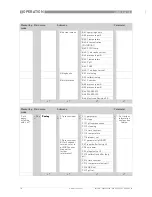
5.2.3 Menu C, setup
C1, process input A
C1, process input A
C1, process input A
C1, process input A
C2, process input B
C2, process input B
C2, process input B
C2, process input B
B2.5
B2.5
B2.5
B2.5
ORP
In this menu the potential of ORP can be simulated. For 2 channel version
only; refer to pH/ORP sensor manual for further information. ONLY if
switched to ORP.
B2.7
B2.7
B2.7
B2.7
pH
In this menu the relative concentration of pH can be simulated. For 2
channel version only; refer to pH/ORP sensor manual for further
information.
Level
Designation / function
Settings / descriptions
This menu groups several functions which allow to display the corresponding actual reading. The shown measurements
are depending on the device configuration.
B4.1
B4.1
B4.1
B4.1
operating hours
This menu shows the operating time of the devices in hours.
B4.2
B4.2
B4.2
B4.2
process input A
In this menu the measurements from process input A can be read.
B4.3
B4.3
B4.3
B4.3
process input B
In this menu the measurements from process input B can be read.
For 2 channel version only; refer to pH/ORP sensor manual for further
information.
INFORMATION!
The signal converter has two process inputs, A and B. Each process input has an own submenu
in this main menu. Process input A is always present, i.e. there is always a board in the interface
"Pos.A" in the connection area. The interface of process input B only has a board with the two
channel signal converter. Be aware that the definition which kind of measurement a process
input can do is defined when ordering the device. The configuration cannot be changed later.
INFORMATION!
Note that the appearance of some submenus depends on the hardware setting and the used
sensor(s).
Level
Designation / function
Settings / descriptions
Process input A and B can be either a sensor 1 or a sensor 2. Further information about the type of sensor 1 or 2 please
refer to MAC 100 manual "Sensor input combinations". Process input A is always present, process Input B can be
present.
Note: The exchange of a sensors 1 with a sensor 2, or vice versa, can only be done by the manufacturer!
Depending on the sensor which is connected to a slot A or B the menu changes.
C1.1
C1.1
C1.1
C1.1
parameter (Cl
2
/ClO
2
/O
3
)
This menu item is for selecting the probe which is connected to process
input A. The entries of this selection depends on the chosen device
configuration. The device configuration is customer specific and set during
production.
C1.9
C1.9
C1.9
C1.9
slope
This menu item is read only.
It shows the slope of the last calibration.
Level
Designation / function
Settings / descriptions


