


ELECTRICAL CONNECTIONS
4
15
OPTISYS CL 1100
www.krohne.com
03/2016 - 4002492302 - MA OPTISYS CL 1100 R03 en
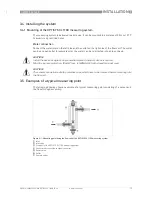
4.3 Connecting the sensor cable to the signal converter
The sensors for free chlorine, chlorine dioxide or ozone are always connected to terminal block
Pos.A of the signal converter. Depending on the configuration of the signal converter, a pH
sensor may be connected to terminal block Pos.B. An external temperature sensor may be
connected to terminal block Pos.A. (For detailed information how to install and configure a pH
and/or a temperature sensor please refer to the pH sensor documentation.)
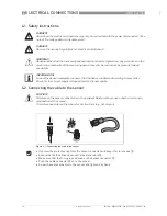
DANGER!
All work on the electrical connections may only be carried out with the power disconnected. Take
note of the voltage data on the nameplate!
INFORMATION!
The sensor cables are prewired to signal converter by the manufacturer.
INFORMATION!
Look at the device nameplate to ensure that the device is delivered according to your order.
Check for the correct supply voltage printed on the nameplate.
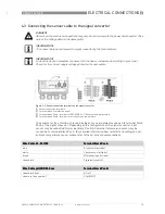
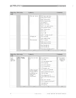
Figure 4-2: Sensor connection terminals on the signal converter
1
Sensor connection terminals
2
Terminal block S (protective earth)
3
Terminal block Pos.A: terminal for OPTISENS CL 1100 sensor and temperature
4
Terminal block Pos.B: terminal for pH sensor and temperature
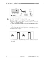
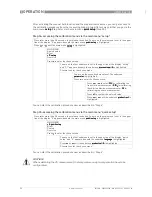
Wire Cable CL-W-1100
Wire Cable CL-W-1100
Wire Cable CL-W-1100
Wire Cable CL-W-1100
Terminal block Pos.A
Terminal block Pos.A
Terminal block Pos.A
Terminal block Pos.A
blue
K (counter electrode)
white
L (reference electrode)
brown
M (measuring electrode)
coax shield
S (protective earth)
Wire Cable pH/ORP-W-Coax
Wire Cable pH/ORP-W-Coax
Wire Cable pH/ORP-W-Coax
Wire Cable pH/ORP-W-Coax
Terminal block Pos.B
Terminal block Pos.B
Terminal block Pos.B
Terminal block Pos.B
coax shield (red)
N (ref.)
coax core (transparent)
O (pH/ORP)


