12
7
Operation of the signal converter
7.1
Table of settable functions
Fct. Text
Description
and settings
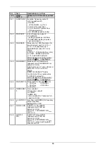
1.0
OPERATION
Main menu 1.0 Operation
1.1.0 BASIC.
PARAM
Submenu 1.1.0 Basis parameters
1.1.1 FULL SCALE
Full-scale range for flowrate Q
100%
,
see Fct. 3.1.1
1.1.2 REV. SCALE
Different range for reverse flow
required? See Fct. 3.1.2
1.1.3 REV.
VALUE Full-scale range for reverse flow
Q
R100%
, see Fct. 3.1.3
1.1.4 ZERO SET.
Zero setting, see Fct. 3.1.4
1.2.0 DISPLAY
Submenu 1.2.0 Display
1.2.1 DISP.
FLOW Unit
for flowrate display,
see Fct. 3.2.1
1.2.2 DISP.
TOTAL. Function of totalizer display,
see Fct. 3.2.2
1.2.3 UNIT TOTAL.
Unit for totalizer display required?
See Fct. 3.2.3
1.2.4 DISP. SP. S.
Display of sound velocity required?
See Fct. 3.2.4
1.2.5 CYCL. DISP.
Cyclic display required?
See Fct. 3.2.5
1.3.0 CUR.
OUTP. I
Submenu 1.3.0 Current output I
1.3.1 TIMECONST.I Time
constant of current output I,
see Fct. 3.3.6
1.3.2 L.F.CUTOFF I
Low-flow cutoff (SMU) for current
output required? See Fct. 3.3.7
1.3.3 CUTOFF
ON
Cutoff “on” value SMU-I,
see Fct. 3.3.8
1.3.4 CUTOFF OFF
Cutoff “off” value SMU-I,
see Fct. 3.3.9
1.4.0 FREQ. OUTP.F Submenu 1.4.0
Frequency output F
1.4.1 PULSRATE
or
PULSE/UNIT
Pulse rate for 100% flowrate or for
sound velocity, see Fct. 3.4.3 or
Pulse value for flowrate unit,
see Fct. 3.4.3
1.4.2 L.F.CUTOFF F Low-flow cutoff (SMU) for frequency
output required? See Fct. 3.4.3
1.4.3 CUTOFF ON
Cutoff “on” value SMU-F,
see Fct. 3.4.7
1.4.4 CUTOFF OFF
Cutoff “off” value SMU-F,
see Fct. 3.4.8
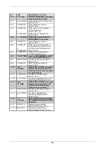
2.0
TEST
Main menu 2.0 Test functions
2.1
TEST DISP.
Carry out display test (Sect. 7.1.1)
Start with
→
key, duration approx. 30
Sec. Test interruption with
↵
key.
2.2
TEST I
Test current output I (Sect. 7.1.2)
•
0 mA
•
4 mA
•
20 mA
•
2 mA
•
10 mA
•
22 mA
Displayed value present directly at
current output. Actual value again
present at output after pressing the
↵
key.
2.3
TEST F
Test frequency output F (Sect. 7.1.3)
•
1 Hz
•
100 Hz
•
10 Hz
• 1000 Hz
Displayed value present directly at
current output. Actual value again
present at output after pressing the
↵
key.
2.4
PROCESSOR
Test microprocessor (Sect. 7.1.4)
Start with
↵
key, duration approx. 2
Sec. End of test:
NO ERROR
or
ERROR
displayed.
Summary of Contents for GFM 700 F
Page 31: ...31 9 ATEX approvals 9 1 GFC 700 F EEx Signal converter...
Page 32: ...32...
Page 33: ...33...
Page 34: ...34 9 2 GFS 700 F EEx Primary head flowmeter...
Page 35: ...35...
Page 36: ...36...

