background image

Kramer Protocol 2000 


37 

37 

For  a  single  machine  controlled  via  the  serial  port,  always  set  M4…M0  =  1,  and  make  sure  that  the  machine  itself  is 

configured as MACHINE NUMBER = 1.  

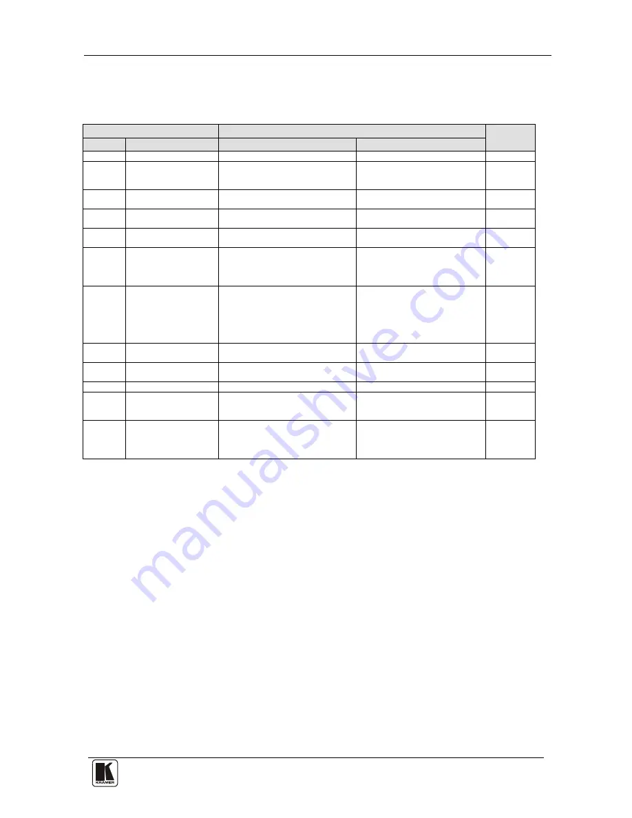
Table 10: Instruction Codes for Protocol 2000 

Note: All values in the table are decimal, unless otherwise stated. 

INSTRUCTION 

DEFINITION FOR SPECIFIC INSTRUCTION 

NOTE 

DESCRIPTION 

INPUT 

OUTPUT 

RESET DEVICE 

SWITCH VIDEO 

Set equal to video input which is to 

be switched 

(0 = disconnect) 

Set equal to video output which is 

to be switched  

(0 = to all the outputs) 

2, 15 

STORE VIDEO 

STATUS 

Set as SETUP # 

0 - to store  
1 - to delete 

2, 3, 15 

RECALL VIDEO 

STATUS 

Set as SETUP # 

2, 3, 15 

REQUEST STATUS 

OF A VIDEO OUTPUT 

Set as SETUP # 

Equal to output number whose 

status is required 

4, 3 

15 

REQUEST WHETHER 

SETUP IS DEFINED / 
VALID INPUT IS 
DETECTED 

SETUP #  
or  
Input # 
 

0 - for checking if setup is defined 
1 - for checking if input is valid 

16 

ERROR / BUSY 

For invalid / valid input (i.e. 

OUTPUT byte = 4 or OUTPUT byte 
= 5),  

this byte is set as the input # 

0 - error 
1 - invalid instruction 
2 - out of range 
3 - machine busy 
4 - invalid input 
5 - valid input 

9, 25 

30 

LOCK FRONT PANEL 

0 - Panel unlocked 
1 - Panel locked 

31 

REQUEST WHETHER 

PANEL IS LOCKED 

16 

56 

CHANGE TO ASCII 

– Protocol 3000l 

19 

61 

IDENTIFY MACHINE  

1 - video machine name 
3 - video software version 
 

0 - Request first 4 digits 
1 - Request first suffix 
 

13 

62 

DEFINE MACHINE  

1 - number of inputs 
2 - number of outputs 
3 - number of setups 

1 - for video 
3 - for SDI 
4 - for remote panel 
5 - for RS-422 controller 

14 

NOTES on the above table: 


NOTE 1

 - When the master switcher is reset, (e.g. when it is turned on), the reset code is sent to the PC. If this code is sent to 

the switchers, it will reset according to the present power-down settings. 


NOTE 2

 - These are bi-directional definitions. That is, if the switcher receives the code, it will perform the instruction; and if 

the instruction is performed (due to a keystroke operation on the front panel), then these codes are sent. For example, if the 

HEX code 

01  

85 

88  

83 

was sent from the PC, then the switcher (machine 3) will switch input 5 to output 8. If the user switched input 1 to output 7 

via the front panel keypad, then the switcher will send HEX codes: 

41 

81 

87 

83 

to the PC. 

When the PC sends one of the commands in this group to the switcher, then, if the instruction is valid, the switcher replies by 

sending to the PC the same four bytes that it was sent (except for the first byte, where the DESTINATION bit is set high).   


NOTE 3

 - SETUP # 0 is the present setting. SETUP # 1 and higher are the settings saved in the switcher's memory, (i.e. those 

used for Store and Recall). 

 
NOTE  4

 - The reply to a "REQUEST"  instruction is as follows: the same instruction and  INPUT codes as were sent are 

returned, and the OUTPUT is assigned the value of the requested parameter. The replies to instructions 10 and 11 are as per 

the  definitions  in  instructions  7  and  8  respectively.  For  example,  if  the  present  status  of  machine  number  5  is  breakaway 

setting, then the reply to the HEX code 

0B 

80 

80 

85 

would be HEX codes 

4B 

80 

81 

85 


Summary of Contents for VS-88HD

Page 1: ...Kramer Electronics Ltd Preliminary USER MANUAL Model VS 88HD 8x8 HD SDI Matrix Switcher...

Page 2: ...Ethernet Port 16 6 7 1 Connecting the ETHERNET Port Directly to a PC Crossover Cable 16 6 7 2 Connecting the ETHERNET Port via a Network Hub Straight Through Cable 18 6 8 Configuring the Ethernet Por...

Page 3: ...11 3 2 Result and Error Codes 32 11 3 3 Basic Routing Commands 32 11 3 4 Preset Commands 33 11 3 5 Operation Commands 33 11 3 6 Machine Information Commands 33 11 3 7 Identification Commands 34 11 3 8...

Page 4: ...cher 6 Table 3 Machine DIP Switch Settings 14 Table 4 DIP Switch Settings 14 Table 5 Genlock Settings 16 Table 6 VS 88HD Technical Specifications 24 Table 7 Communication Parameters 24 Table 8 VS 88HD...

Page 5: ...Power cord2 and rack ears This user manual3 2 Getting Started We recommend that you Unpack the equipment carefully and save the original box and packaging materials for possible future shipment Revie...

Page 6: ...KRAMER SIMPLE CREATIVE TECHNOLOGY Getting Started 2 2 1 Quick Start This quick start chart summarizes the basic setup and operation...

Page 7: ...reference input Switching according to the bi level or tri level genlock3 input according to SMPTE RP 168 The VS 88HD is housed in a 19 1U rack mountable enclosure and is fed from a 100 240 VAC univer...

Page 8: ...oise levels often associated with low quality cables Avoid interference from neighboring electrical appliances that may adversely influence signal quality and position your Kramer VS 88HD away from mo...

Page 9: ...Your VS 88HD 8x8 HD SDI Matrix Switcher 5 Figure 1 VS 88HD 8x8 HD SDI Matrix Switcher...

Page 10: ...r Connects to the genlock source 13 TERM HI Z 75 Pushbutton Press to terminate the genlock source 75 or release for looping 14 LOOP BNC Connector Connects to the genlock connector of the next unit in...

Page 11: ...ocated 15 meters away from the machine This distance can be extended to up to 60 meters when used with three extension cables2 Before using the external IR receiver be sure to arrange for your Kramer...

Page 12: ...KRAMER SIMPLE CREATIVE TECHNOLOGY Installing the VS 88HD in a Rack 8 5 Installing the VS 88HD in a Rack This section provides instructions for rack mounting the unit...

Page 13: ...ple OUTPUT 1 to a non linear editor and OUTPUT 8 to an HD SDI display 3 Set the DIP switches see section 6 4 2 4 Optionally2 connect A genlock source to the GENLOCK BNC connector The LOOP BNC connecto...

Page 14: ...KRAMER SIMPLE CREATIVE TECHNOLOGY Connecting the VS 88HD 10 Figure 2 Connecting the VS 88HD 8x8 HD SDI Matrix Switcher...

Page 15: ...ect A genlock source to the GENLOCK BNC connector The LOOP BNC connector to the GENLOCK connector of the next unit in the line and release the TERM button for looping4 5 Connect a PC and or controller...

Page 16: ...KRAMER SIMPLE CREATIVE TECHNOLOGY Connecting the VS 88HD 12 Figure 3 VS 88HD Dual Link Inputs and Outputs Figure 4 Connecting the Dual Link VS 88HD 8x8 HD SDI Matrix Switcher...

Page 17: ...y during switching1 6 4 Connecting the RS 232 Port You can connect to the VS 88HD via an RS 232 connection using for example a PC Note that a null modem adapter connection is not required To connect t...

Page 18: ...address the device must be reset by turning OFF and ON 6 4 2 Setting the DIP Switches When controlling a unit via the RS 232 or RS 485 ports set the DIP switches on the rear of the unit Figure 5 and...

Page 19: ...ect the B pin on the RS 485 port of the PC to the B pin on the RS 485 port on the rear panel of the VS 88HD Connect the G pin on the RS 485 port of the PC to the G pin on the RS 485 port on the rear p...

Page 20: ...ERNET in the following ways For direct connection to the PC use a crossover cable see section 6 7 1 For connection via a network hub or network router use a straight through cable see section 6 7 2 6...

Page 21: ...l Area Connection Properties window appears 5 Select the Internet Protocol TCP IP and click the Properties Button see Figure 6 Figure 6 Local Area Connection Properties Window 6 Select Use the followi...

Page 22: ...ernet configuration software Extract the file to a folder and create a shortcut on your desktop to the file Follow these steps to configure the port 1 Double click the desktop icon The Connect screen...

Page 23: ...ation If you are controlling a standalone unit via RS 232 or the Ethernet configure the unit as master Mach No 1 see section 6 4 1 6 10 Using the Ethernet Reset Button To reset Ethernet parameters to...

Page 24: ...hoose to work in either the AT ONCE or the CONFIRM modes When the VS 88HD operates in the AT ONCE mode pressing an OUT IN combination implements the switch immediately In the CONFIRM mode the change d...

Page 25: ...and actions no longer require user confirmation 7 1 5 Switching in the CONFIRM Mode To switch in the CONFIRM mode when the TAKE button is illuminated do the following 1 Press an OUT IN combination The...

Page 26: ...mode and manually scan all the input output configurations until you locate it 7 1 8 Locking the Front Panel Lock the front panel buttons to prevent unwanted key presses from changing the existing set...

Page 27: ...er offers control software that can do this You can download free software from the Kramer Electronics Web site For an explanation of all KRAMER 3000 commands see section 10 2 For an explanation of al...

Page 28: ...Power cord rack ears and IR remote control transmitter OPTIONS External remote IR receiver cable 9 Communication Parameters The following table lists the communication parameters for Protocol 2000 an...

Page 29: ...HD using any one of the following connections Connect a serial cable from an RS 232 9 pin D sub rear panel port on the PC to the VS 88HD as explained in section 6 4 Connect an RJ 45 Ethernet cable fro...

Page 30: ...ECHNOLOGY Using the P3K Wizard 26 Figure 11 Connect Window 4 Choose the appropriate type of connection Ethernet BY IP BY NAME or SERIAL USB and click OK The Connect window disappears and the Device Pr...

Page 31: ...he white fields as required and click SET 10 2 Updating the VS 88HD Firmware The VS 88HD uses a microcontroller that runs firmware located in FLASH memory The latest version of firmware and installati...

Page 32: ...the front panel buttons or by transmitting protocol commands To switch protocols using the front panel buttons To choose Protocol 2000 press LOCK and OUT 2 at the same time To choose the Protocol 300...

Page 33: ...ter_1 Parameter_2 CR 11 2 3 Command String Formal syntax with commands concatenation and addressing Start Address Body Delimiter Destination_id Command_1 Parameter1_1 Parameter1_2 Command_2 Parameter2...

Page 34: ...for K NET K NET Device ID followed by Query sign follows some commands to define a query request Message closing character CR For host messages carriage return ASCII 13 CRLF For machine messages carr...

Page 35: ...hen chaining commands enter the message starting character and the message closing character only once at the beginning of the string and at the end Commands in the string do not execute until the clo...

Page 36: ...1 IN 2 Parameter Description IN Input number or 0 to disconnect output Connection character between in and out parameters OUT Output number or for all outputs Examples Switch video input 2 to output...

Page 37: ...STO 5CR PRST STR 5 OKCRLF Recall video connections from preset 3 PRCL 3CR PRST RCL 3 OKCRLF Show source of video output 2 from preset 3 PRST VID 3 2CR PRST VID 3 4 2 CRLF 11 3 5 Operation Commands Co...

Page 38: ...IP_ADDRESS RESULT Read IP address NET IP Short form NTIP NET IP IP_ADDRESS Read MAC address NET MAC Short form NTMC NET MAC MAC_ADDRESS Set subnet mask NET MASK SUBNET_MASK Short form NTMSK NET MASK S...

Page 39: ...10 IN 2 10 18 11 10 10 18 18 10 10 18 18 10 10 18 18 10 10 18 18 10 10 18 18 10 10 18 18 10 10 18 10 10 IN 3 10 18 11 10 10 18 18 10 10 18 18 10 10 18 18 10 10 18 18 10 10 18 18 10 10 18 18 10 10 18 1...

Page 40: ...YTE Bit 7 Defined as 1 I6 I0 INPUT When switching i e instruction codes 1 and 2 the INPUT 7 bits is set as the input number which is to be switched Similarly if switching is done via the machine s fro...

Page 41: ...ber of setups 1 for video 3 for SDI 4 for remote panel 5 for RS 422 controller 14 NOTES on the above table NOTE 1 When the master switcher is reset e g when it is turned on the reset code is sent to t...

Page 42: ...d the version number would be HEX codes 7D 83 85 81 i e 128dec 3dec for 2nd byte 128dec 5dec for 3rd byte If the OUTPUT is set as 1 then the ASCII coding of the lettering following the machine s name...

Page 43: ...39 39...

Page 44: ...st information on our products and a list of Kramer distributors visit our Web site www kramerelectronics com where updates to this user manual may be found We welcome your questions comments and feed...

Reviews: