background image

KRAMER:  SIMPLE CREATIVE TECHNOLOGY


Installing the VS-81DVI-R on a Rack 


5  Installing the VS-81DVI-R on a Rack 

This section describes what to do before installing on a rack and how to rack 

mount. 


Before Installing on a Rack 

Before installing on a rack, be sure that the environment is 

within the recommended range: 
Operating temperature range  +5 to +45 Deg. Centigrade 
Operating humidity range 

5 to 65 % RHL, non-condensing 

Storage temperature range 

-20 to +70 Deg. Centigrade 

Storage humidity range 

5 to 95% RHL, non-condensing 


 CAUTION!! 

When installing on a 19" rack, avoid hazards by taking care 

that: 

1


It is located within the recommended environmental 

conditions, as the operating ambient temperature of a 

closed or multi unit rack assembly may exceed the room 

ambient temperature. 

2


Once rack mounted, enough air will still flow around the 

machine. 

3


The machine is placed straight in the correct horizontal 

position. 

4


You do not overload the circuit(s). When connecting the 

machine to the supply circuit, overloading the circuits 

might have a detrimental effect on overcurrent 

protection and supply wiring. Refer to the appropriate 

nameplate ratings for information. For example, for fuse 

replacement, see the value printed on the product label. 

5


The machine is earthed (grounded) in a reliable way 

and is connected only to an electricity socket with 

grounding. Pay particular attention to supply 

connections other than direct connections to the branch 

circuit (for example, the use of power strips), and that 

you use only the power cord that is supplied with the 

machine.


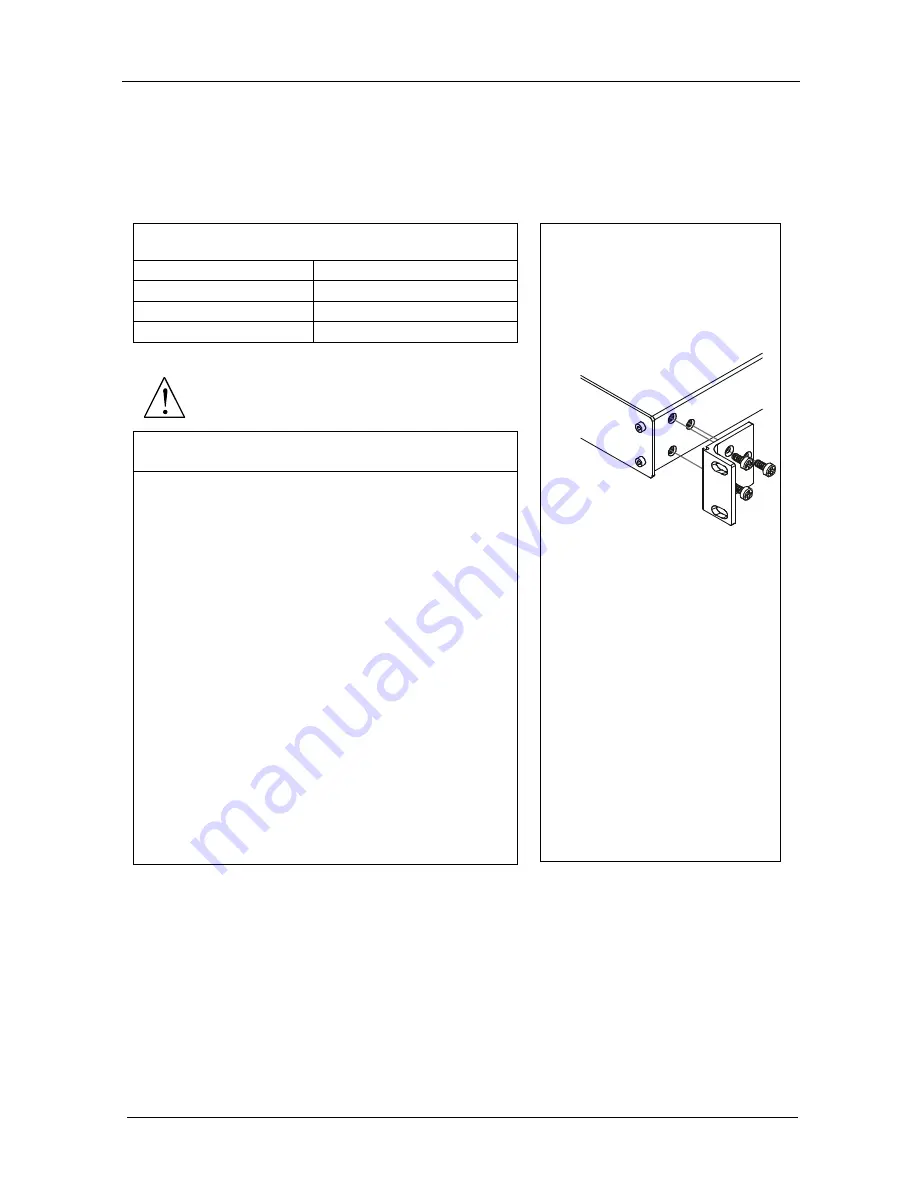
How to Rack Mount 

To rack-mount the machine: 
1


Attach both ear brackets to the 

machine. To do so, remove the 

screws from each side of the 

machine (3 on each side), and 

replace those screws through 

the ear brackets. 


2


Place the ears of the machine 

against the rack rails, and 

insert the proper screws (not 

provided) through each of the 

four holes in the rack ears. 

Note that: 

 In some models, the front panel 

may feature built-in rack ears 

 Detachable rack ears can be 

removed for desktop use 

 Always mount the machine in the 

rack before you attach any cables or 

connect the machine to the power 

 If you are using a Kramer rack 

adapter kit (for a machine that is not 

19"), see the Rack Adapters user 

manual for installation instructions 

(you can download it at: 

http://www.kramerelectronics.com) 


Summary of Contents for VS-81DVI-R

Page 1: ...Kramer Electronics Ltd USER MANUAL Model VS 81DVI R 8x1 DVI Switcher...

Page 2: ...r 8 Figure 3 Connecting a PC without using a Null modem Adapter 9 Figure 4 RJ 45 PINOUT 10 Figure 5 Local Area Connection Properties Window 11 Figure 6 Internet Protocol TCP IP Properties Window 11 Fi...

Page 3: ...ER on again The front panel display initially shows a blinking E followed by the input numbers from 1 to 8 that blink until the unit has completed reading the EDID While the machine is acquiring the E...

Page 4: ...rial Port Manager Kramer RC IR1 Infra Red Remote Control Transmitter3 including the required battery and a separate user manual4 Power cord This user manual4 2 Getting Started We recommend that you Un...

Page 5: ...s may be cascaded Automatically reads and stores in non volatile memory the EDID1 block of the display device Does not support HDCP High Definition Digital Content Protection Includes a MUTE button to...

Page 6: ...via a particular server or workstation of data HTML pages or e mails that is sent in packets across the Internet Every device connected to an IP network must have a unique IP address This address is...

Page 7: ...Your VS 81DVI R 8x1 Switcher KRAMER SIMPLE CREATIVE TECHNOLOGY 4 Figure 1 VS 81DVI R 8x1 DVI Switcher...

Page 8: ...input 1 6 PANEL LOCK Button Press to disengage the front panel buttons Table 3 VS 81DVI R 8x1 DVI Switcher Rear Panel Features Feature Function 7 INPUT DVI I Connectors Connect to the DVI D sources f...

Page 9: ...nt protection and supply wiring Refer to the appropriate nameplate ratings for information For example for fuse replacement see the value printed on the product label 5 The machine is earthed grounded...

Page 10: ...3 If required connect a PC and or controller to the RS 232 port see section 6 1 and or the ETHERNET port see section 6 2 4 Connect the power connector to the mains electricity After turning on the po...

Page 11: ...KRAMER SIMPLE CREATIVE TECHNOLOGY Connecting a VS 81DVI R 8x1 DVI Switcher 8 DVI Graphics Source 8 RS 232 DVI Display DVI Graphics Source 1 Figure 2 Connecting a VS 81DVI R 8x1 DVI Switcher...

Page 12: ...9 wire flat cable to the RS 232 DB9 port on your PC To connect a PC to the VS 81DVI R unit without using a Null modem adapter Connect the RS 232 DB9 port on your PC to the RS 232 DB9 rear panel port...

Page 13: ...J 45 PINOUT EIA TIA 568A Side 1 EIA TIA 568B Side 2 PIN Wire Color PIN Wire Color 1 White orange 1 White green 2 Orange 2 Green 3 White green 3 White orange 4 Blue 4 Blue 5 White blue 5 White blue 6 G...

Page 14: ...rnet Protocol TCP IP and click the Properties Button see Figure 5 Figure 5 Local Area Connection Properties Window 6 Select Use the following IP Address and fill in the details as shown in Figure 6 7...

Page 15: ...as described in section 6 2 1 2 Insert the CD ROM in the CD ROM drive double click the SetFC11_xx exe1 file and follow the on screen instructions2 Both the Ethernet Configuration Manager and the Virt...

Page 16: ...ion 6 Device Network Settings Area DHCP 1 Mode Check Box When selected configures the Ethernet port to obtain an IP address automatically from the DHCP server When cleared manual configuration of the...

Page 17: ...Virtual Serial Port Manager Application The Virtual Serial Port Manager window appears see Figure 8 Figure 8 The Virtual Serial Port Manager Window 2 Press the Add VSP button to add a serial port and...

Page 18: ...connection according to your virtual serial port connections see Figure 11 Figure 11 The Port Window Selecting a Virtual Serial Port 6 3 2 Setting an Ethernet Connection If the control application ca...

Page 19: ...5Vpp TTL RESOLUTION Up to UXGA POWER SOURCE 100 264VAC 50 60Hz CONTROLS Front panel buttons Infra red remote control transmitter RS 232 Ethernet DIMENSIONS 19 inch W 7 inch D 1U H WEIGHT 2 5 kg 5 5 l...

Page 20: ...riginal dated invoice or a copy must be presented as proof of warranty coverage and should be included in any shipment of the product Please also include in any mailing a contact name company address...

Page 21: ...For the latest information on our products and a list of Kramer distributors visit our Web site www kramerelectronics com where updates to this user manual may be found We welcome your questions comme...

Reviews: