background image

Your VS-808YC 8x8 s-Video / Audio Matrix Switcher 


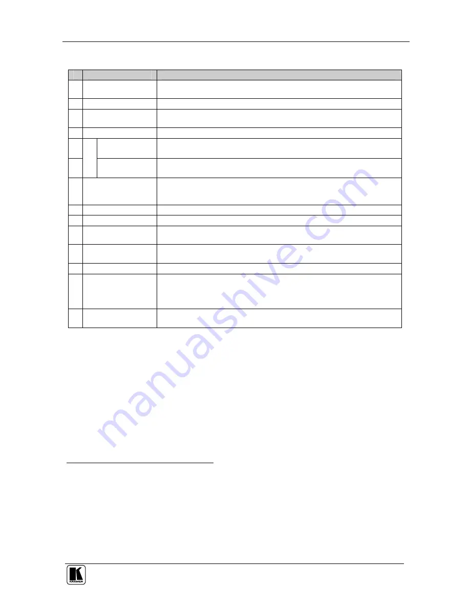
Table 1: Front Panel VS-808YC 8x8 s-Video / Audio Matrix Switcher Features 

Feature 

Function 

IR Receiver


The LED is illuminated when receiving signals from the Infrared remote 

control transmitter 

Power

 Switch 

Illuminated switch for turning the unit ON or OFF 

OFF

 Button 

An 

OFF

-

OUT

 combination disconnects that output from the inputs; an 

OFF

-

ALL

 combination disconnects all the outputs 

ALL

 Button 

Pressing 

ALL

 followed by an 

INPUT

 button, connects that input to all outputs

1


OUTPUT 

Buttons  Select the output to which the input is switched 


S

E

LE

C

T

O

R


INPUT 

Buttons 

Select the input to switch to the output 
 

TAKE 

Button


Pressing 

TAKE

 toggles the mode between the 

CONFIRM

 mode

2

 and the 

AT ONCE

 mode (user confirmation per action is unnecessary). When in 

TAKE mode, pressing TAKE implements the action 

VIDEO 

Button


When pressed

3

 actions relate to video, and display shows video status 

AUDIO

 Button 

When pressed

4

 actions relate to audio, and display shows audio status 

10 

AFV 

Button


When pressed

5

 actions relate to video and audio channels. Audio channels 

follow the video channels 

11 

STATUS 

7-segment


Display 

Displays the selected input switched to the output (marked above each 

input)

6


12 

STO

 (STORE) Button  Pressing STO followed by an output button stores the current setting

7


13 

RCL

 (

RECALL

Button


Pressing the 

RCL

 button and the corresponding OUTPUT key recalls a 

setup from the non-volatile memory. The stored status blinks. Pressing a 

different OUTPUT button lets you view

8

 another setup. After making your 

choice, pressing the 

RCL

 button again implements the new status 

14 

LOCK

 Button


Engages/disengages the front panel switches. Button is illuminated when 

front panel is locked 


1 For example, press ALL and then Input button # 2 to connect input # 2 to all the outputs 
2 When in Confirm mode, the TAKE button illuminates 
3 The VIDEO button is illuminated when the video breakaway mode is selected 
4 The AUDIO button is illuminated when the audio breakaway mode is selected 
5 The AFV button is illuminated when the AFV mode is selected 
6 Also displays the firmware version number and the MACHINE #. Refer to section 8.1 
7 For example, press STO and then the Output button # 3 to store in Setup # 3 
8 Only view, nothing is implemented at this stage 

Summary of Contents for VS-808YC

Page 1: ...Kramer Electronics Ltd USER MANUAL Model VS 808YC 8x8 s Video Audio Matrix Switcher...

Page 2: ...y Option 18 8 2 1 Setting the Audio Follow Video Option 18 8 2 2 Setting the Breakaway Option 18 8 3 Switching OUT IN Combinations 18 8 4 Confirming Settings 19 8 4 1 Toggling between the AT ONCE and...

Page 3: ...Unit Characteristics 17 Figure 12 Storing and Recalling using the Input Output Buttons 20 Figure 13 Splash Screen 24 Figure 14 Atmel Flip Window 24 Figure 15 Device Selection Window 25 Figure 16 Devi...

Page 4: ...em adapter Windows based Kramer control software2 Infrared remote control transmitter including the required battery and a separate user manual3 This user manual3 2 Getting Started We recommend that y...

Page 5: ...KRAMER SIMPLE CREATIVE TECHNOLOGY Getting Started 2...

Page 6: ...ering with the front panel Control the VS 808YC using the front panel buttons or remotely via RS 232 or RS 485 serial commands transmitted by a touch screen system PC or other serial controller The Kr...

Page 7: ...KRAMER SIMPLE CREATIVE TECHNOLOGY Your VS 808YC 8x8 s Video Audio Matrix Switcher 4 Figure 1 VS 808YC 8x8 s Video Audio Matrix Switcher...

Page 8: ...ssed 5 actions relate to video and audio channels Audio channels follow the video channels 11 STATUS 7 segment Display Displays the selected input switched to the output marked above each input 6 12 S...

Page 9: ...IR remote controller instead of using the front panel IR receiver 2 22 FLASH PROG Button Push in 3 for Program to upgrade to the latest Kramer firmware see section 9 or release for Normal the factory...

Page 10: ...be located 15 meters away from the machine This distance can be extended to up to 60 meters when used with three extension cables2 Before using the external IR receiver be sure to arrange for your Kra...

Page 11: ...ly wiring Refer to the appropriate nameplate ratings for information For example for fuse replacement see the value printed on the product label 5 The machine is earthed grounded in a reliable way and...

Page 12: ...OUTPUTS terminal block connectors to the balanced stereo audio acceptors for example power amplifiers and speakers 3 Set the DIP switches see section 6 5 4 If required Connect a PC to the RS 232 port...

Page 13: ...KRAMER SIMPLE CREATIVE TECHNOLOGY Connecting the VS 808YC 10 Figure 3 Connecting the VS 808YC 8x8 s Video Audio Matrix Switcher...

Page 14: ...e RS 232 9 pin D sub port on your PC To connect a PC to the VS 808YC unit without using a Null modem adapter Connect the RS 232 9 pin D sub port on your PC to the RS 232 9 pin D sub rear panel port on...

Page 15: ...the VS 808YC unit Connect the B PIN on the RS 485 rear panel port of the RC 3000 to the B PIN on the RS 485 rear panel port of the VS 808YC unit If shielded twisted pair cable is used the shield may b...

Page 16: ...input output connection Figure 6 Connecting the Balanced Stereo Audio Input Output Figure 7 illustrates how to wire an unbalanced input Figure 7 Connecting the Unbalanced Stereo Audio Input Figure 8 i...

Page 17: ...ich VS 808YC unit is being controlled when several VS 808YC units connect to a PC or serial controller Set the MACHINE on a VS 808YC unit via DIPS 1 2 3 and 4 according to Table 5 When using a stand a...

Page 18: ...to the PC using the Null modem adapter provided with the machine recommended as section 6 2 describes 3 Connect the RS 485 terminal block port on the first VS 808YC unit to the RS 485 port on the sec...

Page 19: ...olling via RS 232 and RS 485 16 ON 1 8 7 4 6 3 5 2 MACH RS 485 TERM ON 1 8 7 4 6 3 5 2 MACH RS 485 TERM Enlarged View ON 1 8 7 4 6 3 5 2 MACH RS 485 TERM Figure 10 Cascading Individual Units in a Cont...

Page 20: ...nfrared remote control transmitter 8 1 Displaying Unit Characteristics Switching on and or resetting1 the VS 808YC unit momentarily displays the following characteristics in the front panel 7 segment...

Page 21: ...ress the TAKE button to confirm the modification reconfiguring the audio according to the video 8 2 2 Setting the Breakaway Option To set the Breakaway option Press either the AUDIO for audio control...

Page 22: ...1 Toggling between the AT ONCE and CONFIRM Modes To toggle between the AT ONCE and CONFIRM modes do the following 1 Press the unlit TAKE button to toggle from the AT ONCE mode in which the TAKE button...

Page 23: ...ns as Figure 12 illustrates Figure 12 Storing and Recalling using the Input Output Buttons2 8 5 1 Storing an Input Output Configuration To store the current status in memory do the following 1 Press t...

Page 24: ...ion do the following 1 Press the STO and RCL buttons simultaneously Both the STO and RCL buttons blink 2 Press the appropriate Input Output button This erases that specific input output configuration...

Page 25: ...do the following Press INPUT buttons 1 2 and 3 simultaneously for 3 seconds The VS 808YC unit resets to the current status momentarily displaying3 the unit characteristics as section 8 1 describes 8...

Page 26: ...Extract the file FLIP_VS 808YC zip to a folder for example C Program Files Kramer Flash 3 Create a shortcut on your desktop to the file FLIP EXE 9 2 Connecting the PC to the RS 232 Port Before install...

Page 27: ...EXE The Splash screen appears as follows Figure 13 Splash Screen 2 After a few seconds the Splash screen is replaced by the Atmel Flip window Figure 14 Atmel Flip Window 3 Press the keyboard shortcut...

Page 28: ...igure 15 Device Selection Window 4 Click the button next to the name of the device and select from the list AT89C51RD2 AT89C51RD2 T89C51RD2 Figure 16 Device Selection Window 5 Click OK and select Load...

Page 29: ...mmunication RS232 command from the Settings menu or press the keys Alt SCR The RS232 window appears Change the COM port according to the configuration of your computer and select the 9600 baud rate Fi...

Page 30: ...eration is completed all 4 check boxes will be colored green and the status bar message Memory Verify Pass appears2 VS808YC hex A Figure 20 Atmel Flip Window Operation Completed 10 On the rear panel r...

Page 31: ...her INPUTS 8 s Video 1 Vpp 75 Y 0 3Vpp 75 C on 4 pin connectors 8 balanced stereo audio 4dBm 50k on detachable terminal blocks OUTPUTS 8 s Video 1 Vpp 75 Y 0 3Vpp 75 C on 4 pin connectors 8 balanced s...

Page 32: ...via RS 232 RS 485 Switching Audio Channels Switching Video Channels OUT 8 OUT 7 OUT 6 OUT 5 OUT 4 OUT 3 OUT 2 OUT 1 OUT 8 OUT 7 OUT 6 OUT 5 OUT 4 OUT 3 OUT 2 OUT 1 02 02 02 02 02 02 02 02 IN 1 02 02...

Page 33: ...below INSTRUCTION NO is the value to be set for N5 N0 2nd BYTE Bit 7 Defined as 1 I6 I0 INPUT When switching ie instruction codes 1 and 2 the INPUT 7 bits is set as the input number which is to be sw...

Page 34: ...ETHER SETUP IS DEFINED Set as SETUP 0 8 16 ERROR BUSY 0 0 error 1 invalid instruction 2 out of range 9 30 LOCK FRONT PANEL 0 Panel unlocked 1 Panel locked 0 2 31 REQUEST WHETHER PANEL IS LOCKED 0 0 16...

Page 35: ...he OUTPUT is set as 0 and the INPUT is set as 1 2 5 or 7 the machine will send its name The reply is the decimal value of the INPUT and OUTPUT For example for a 2216 the reply to the request to send t...

Page 36: ...o 10013dec 271Dhex first send HEX codes 3F 80 CE 81 followed by HEX codes 16 86 9D 81 NOTE 20 To store data in the non volatile memory of the unit e g the EEPROM for saving SETUPS The EEPROM address i...

Page 37: ...er lightning orotheractsofnature ii Product modification orfailureto followinstructionssupplied with the product iii Repairorattemptedrepairby anyone not authorized byKramer iv Anyshipment ofthe produ...

Page 38: ...or the latest information on our products and a list of Kramer distributors visit our Web site www kramerelectronics com where updates to this user manual may be found We welcome your questions commen...

Reviews: